

Keeping in Rhythm with the Power
The earliest production cars created, including the Benz Patent Motor Car, no. 1 as discussed in Old School Heart with New School Brains, needed methods to transfer power from their engines to their drive wheels. These early cars utilized various mechanical pieces that would connect their engines to the cars’ wheels to move. As cars evolved and their performance improved, so did the design and complexity of their mechanical components which helped make these early cars drive. Cars began to travel farther and faster, making the need for increased efficiency necessary. This required an overhaul of the design and created a component cars ever since have used and needed: the automotive transmission.
Throughout the 1920’s and 1980’s many cars utilized three-speed manual transmissions. This adaptation allowed many people to drive farther and faster due to improved gear ratios. Cars which used three-speed manual transmissions include the 1970 Ford Fairlane, the 1955 Chevrolet Bel Air, and the 1960 Dodge Polara. Cars such as these were known as quintessential family cars that could take families across the United States during the post-war boom in the United States. However, not even three-speed manuals would be sufficient for many for too much longer.
When General Motors introduced their Hydra-Matic transmission in 1940, however, the future of automotive travel would change the world over. Originally developed by General Motors’ Oldsmobile division, this innovative transmission made driving more comfortable and easy thanks in large part to the transmission automatically selecting gears for the driver. By the 1960’s and 1970’s, more automotive manufacturers created their own automatic transmissions as an upgrade from the standard three-speed manual transmission.
As for supercars and high-performance cars, though, automatic transmissions weren’t able to change gears quick enough for the acceleration and performance demands these cars required. Thus, many supercars and hypercars had manual transmission even into the mid to late 1990’s. Examples of these kinds of cars include the Ferrari F50 and the vaunted McLaren F1.
However, as the new millennium approached and many feared the arrival of the Y2K bug that would shock many systems worldwide, new types of transmissions were on the horizon that would improve power delivery. For the Ferrari F50’s replacement, the Ferrari Enzo, this would mean that instead of a manual transmission, it would receive instead an automated manual—or single-clutch—transmission (AMT). This transmission would allow the driver to select a gear in as little as 150 milliseconds. In the Ferrari Enzo, this was accomplished through shift paddles on the steering wheel. Coming from an era where the only way to drive a supercar or hypercar was mainly by a manual transmission, having such a car only use an AMT rather than have it as an option like it was in the 1997 Ferrari F355 was a major innovative milestone.
Other automotive manufacturers of high-performance cars followed suit in utilizing semi-automatic transmissions, including the Lamborghini Murciélago, the Lamborghini Gallardo, the Ferrari 599 GTO, and the Lexus LFA. This quickly improved performance for all high-performance cars due to quicker shift times allowing for quicker acceleration and quicker lap times. As with all things in the high-performance automotive world, there would be another transmission which would make shifting seamless and almost instantaneous.
Lo and behold! The dual-clutch transmission (DCT) is here! Even though the first production car to use this transmission was none other than the 2003 Volkswagen Golf R32, DCTs have become a staple in many high-performance supercars and hypercars, including the upcoming McLaren W1, the Ferrari F80, and the C8 Chevrolet Corvette ZR1/ZR1X.
For electric-powered supercars and hypercars which make continuous power, AMTs and DCTs would not be sufficient. A transmission would need to be created which fit the power delivery profile of these high-powered electric supercars and hypercars. These transmissions are known as single-gear transmissions and are seen in supercars and hypercars such as the Rimac Nevera R. Just as the name implies, it’s one gear which manages the power delivery from the car’s electric motor(s) which explains why these cars seem to keep going long after the driver presses the drive pedal all the way down to the floor.
As with all cars, transmissions only do part of the work. This is where drivetrains including front-wheel drive (FWD), rear-wheel drive (RWD) and all-wheel drive (AWD) come into play. These drivetrains are designed to transfer power and torque from the transmission to either the front wheels (FWD), rear wheels (RWD), or all four wheels (AWD).
How, then, does all of this work? How do engineers know which transmission type to use and what type of drivetrain to make the supercar or hypercar with? Before we begin, let’s get a general understanding first of how drivetrains are designed and engineered to best fit the supercar’s or hypercar’s intended function.
A Mechanical Symphony
It always helps to get a general overview of how moving parts in a unit work in conjunction with each other. This idea can be applied to a supercar’s or hypercar’s transmission and drivetrain. In terms of the main function of the drivetrain, its purpose is to maximize the power from the engine to the driving wheels in the supercar or hypercar and minimize power losses. The power from the engine is transferred to the transmission which goes from the transmission's input shaft to its output shaft. The power from the output shaft is then directed to the supercar’s or hypercar’s driveshaft which is then transferred to the differentia(s) connected to the driving wheels of the car. The differential contains what is called a final drive, where the car’s torque is multiplied. Here are some general diagrams showing how the power is transferred from the engine to the car’s drive wheels:
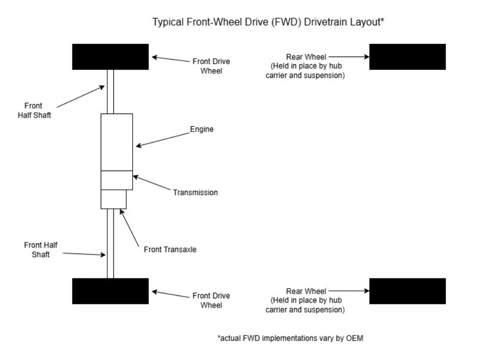
Figure 1: Typical front-wheel drive (FWD) drivetrain layout
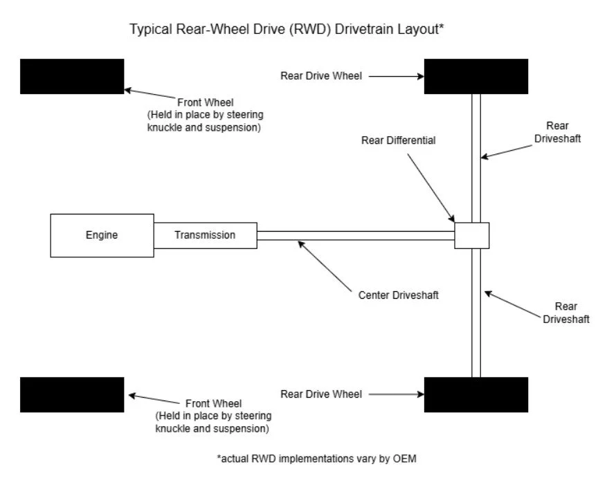
Figure 2: Typical rear-wheel drive (RWD) drivetrain layout
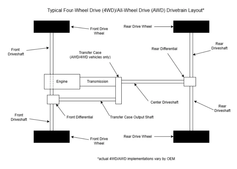
Figure 3: Typical four-wheel drive (4WD)/all-wheel drive (AWD) drivetrain layout
These are typical setups for cars that have internal combustion engines (ICE). It is important to keep in mind that the most efficient drivetrains are able to minimize power losses throughout the drivetrain. Automakers of supercars and hypercars are constantly refining their drivetrains and are constantly using lightweight materials such as aluminum or even carbon fiber in order to conserve weight and decrease the energy needed to rotate the various gears and shafts in the system.
Other cars, however, have drivetrains which utilize a more direct method of transferring power from the engine to the wheels, thereby increasing drivetrain efficiency. This method is found mainly in electric vehicles which have one or more electric motors. This method involves one or more electric motors with accompanying reduction gears and differentials, which usually results in more direct power and less drivetrain losses. Designing and engineering cars with this drivetrain setup allows for performance benefits such as improved acceleration and fuel efficiency since the motor(s) do not have to work as hard.
Regardless of which transmission a supercar or hypercar with an ICE uses, the fundamentals remain the same: using an input shaft and output shaft to transfer power via a series of precision-crafted gears. So, how do input and output shafts work exactly? Let’s examine how both shafts operate inside the transmission.
Input Equals Output
As stated previously, transmissions contain both input and output shafts to transfer power. The way these shafts operate is important to the way the hypercar or supercar performs under heavy acceleration or top speed runs. Optimizing both the input and output shafts in these transmissions is the difference between great performance and superior performance. Let’s see how input shafts contribute to performance.
The input shaft connects directly to the supercar’s or hypercar’s engine. This is the point in the drivetrain where the maximum power from the car’s engine is transferred to the drivetrain. The car’s power is measured by using the following formula:
P = T * ⍵
P: Power (Horsepower)
T: Torque (lb*ft or N*m)
⍵: Angular Velocity (rad/s)
⍵ = Δ𝛳/Δt
Δ𝛳: Change in angle
measurement
Δt: Change in time
Drivetrain engineers utilize the engine’s power to see which type of transmission the car should have and how power will be transferred to the input shaft. Furthermore, this will determine if the input and output shafts will have four, six, or even ten gears on them.
The output shaft is the second shaft in the transmission which is responsible for transmitting power to the car’s driveshaft. This is the component which transfers power from the input shaft to the output shaft. This changes as the gears on the output shaft change due to driver input and system demand.
One way of determining if the transmission setup will benefit the car or not is by determining the car’s transmission ratio. This is accomplished by comparing the angular velocities and speeds of both the input shaft and the output shaft. Here is how it’s measured:
i_G = ⍵_1/⍵_2 = n_1/n_2
i_G: Transmission Ratio
⍵_1: Angular velocity of input shaft (rad/s)
⍵_2: Angular velocity of output shaft (rad/s)
n_1: Input shaft speed
n_2: Output shaft speed
i_G > 0: input and output shafts rotating in same direction
i_G < 0: input and output shafts rotating in different directions
|i_G| > 1: speed reducing ratio
|i_G| < 1: speed increasing ratio
As the transmission moves from the lower gears to the higher gears, iG will get lower, allowing the car to reach higher speeds at higher gears. This is also a reason why many newer models have transmissions with six speeds or greater. These transmissions allow the power from the engine to more efficiently be used to achieve higher speeds, resulting in less fuel consumption and greater fuel efficiency.
From the beginning to the end of the transmission, there are mechanical components known as bearings. These help hold both the input and output shafts in place while the input and output shafts rotate and transmit power from the engine to the drive shaft. Engineers need to ensure these bearings not only help the shafts stay in place but are able to allow the shafts to rotate at the necessary angular velocities to have the vehicle move at the desired speed.
One method engineers use to help make this determination is by studying the critical speed of these components. Critical speed is the speed at which rotating components begin to vibrate and can potentially cause damage to the transmission and its various components. Understanding critical speed and all the variables which influence this phenomenon is foundational to the long-term optimum success of transmissions in supercars and hypercars. Here are two formulas automotive engineers may use to determine critical speed:
Load applied by gear to center of shaft:
N = 3,100,850 * (d^(2) / ( l *√(W * l))
N: critical speed (RPM)
d: diameter of shaft (in inches)
l: distance between centers of bearings (in inches)
W: load applied to shaft (in lbs)
Load applied by gear outside the center of shaft:
N = 387,000 * ((d * l)/(a * b)) * √(l / (W * a * b))
N: critical speed (RPM)
d: diameter of shaft (in inches)
l: distance between centers of bearings (in inches)
W: load applied to shaft (in lbs)
a: distance between Bearing 1 and load
b: distance between Bearing 2 and load
As with many concepts in engineering, context is key. It is important to understand where the critical speed is being evaluated in the transmission to accurately determine at what speed the transmission becomes unsafe to function and operate.
The types of bearings used to hold input and output shafts are known as rotational bearings. These bearings contain lubricated internal rolling elements—like cylinders and tapered rollers—inside to help facilitate rotation of the shaft while also using the external housing on the bearing to hold the shaft in place. There are various rotational bearing designs, but all utilize this design concept. Ball bearings are also used in automotive transmissions and operate in the same manner as roller bearings with the exception that the internal rolling elements are metallic spheres rather than tapered rollers and cylinders.
It’s important to note that bearings will wear over time due to repeated use. One way engineers determine the lifespan of bearings is by utilizing the following formula:
L_10 = (C/P)^(p) * (10^(6) revolutions)
L_10: service life of bearings in number of revolutions
90% of the value in a large group of similar bearings
C: basic dynamic load rating (in lbs or N)
P: equivalent bearing load (in lbs or N)
p: service life exponent ( p = 3 for ball bearings; p = 10/3
for roller bearings)
Utilizing formulas such as these help engineers understand how long roller and ball bearings will last.
Along with bearings, it is important to keep all moving parts in the transmission and drivetrain well lubricated for optimal performance. Similar to how engine oil lubricates the moving parts in an engine as discussed in Old School Heart with New School Brains, transmissions use transmission fluid to reduce friction and preserve the moving internal components of the transmission. However, different supercars and hypercars use different types of transmission fluids for their transmissions, which can be viewed here.
A Proportional Response to Power
As discussed previously, transmissions help relay power from the engine to the car’s drive wheels. One way engineers measure how power is transferred is by measuring the speed of the input shaft and comparing it to the speed of the output shaft. Here is a formula automotive engineers use to measure these speeds:
𝜈 = n_2/n_1
𝜈: speed conversion factor
n_1: input shaft speed
n_2: output shaft speed
As is the case with modern transmissions, the higher the gear, the higher the 𝜈. This is also a reason why higher gears in supercars and hypercars help these vehicles achieve greater fuel efficiency.
Another metric automotive engineers may use to determine the power efficiency of the transmission is through the supercar’s or hypercar’s torque conversion factor. This allows engineers to see how much torque is being transmitted from the input shaft to the output shaft. Below is how the torque conversion factor is calculated:
𝜇 = T_2/T_1
𝜇: Torque conversion factor
T_1: Torque from input shaft
T_2: Torque from output shaft
Understanding how torque—or the force exerted on an object a certain distance away from the object’s rotational center—can be measured and used to determine transmission efficiency is key in this scenario.
Some automotive engineers may compare input/output shaft ratios between the supercar’s or hypercar’s highest gear and its lowest gear. This comparison is known as either the range of ratios or the supercar’s or hypercar’s overall gear ratio. Here is how this value is calculated:
i_G, tot = (i_G, max)/(i_G, min) = i_1/i_z
i_G, tot: Overall gear ratio
i_G, max: Highest value for input/output shaft ratio based on transmission gear
i_G, min: Lowest value for input/output shaft ratio based on transmission
gear
i_z: 1st gear
i_z: zth gear
Depending on the intended function of the supercar’s or hypercar’s transmission, the overall gear ratio may differ from other supercars or hypercars and will need to be determined by the manufacturer.
While these formulas can help automotive engineers get the most power from the internal combustion engines (ICE) in these supercars and hypercars, this is not an exhaustive list of methods automotive engineers use. It is of utmost importance for automotive engineers to refer to standards set by industry experts and experienced personnel at each original equipment manufacturer (OEM). Such standards help automotive engineers design and create transmissions that maximize the lifespan of the supercar or hypercar while also minimizing unnecessary costs and lost time.
The Shifting Force
Many automotive transmissions contain multiple gears to improve acceleration, top speed and fuel efficiency. Ensuring the gears in these transmissions last a long time is of utmost importance to automotive engineers. One factor automotive engineers take into account when designing and engineering long-lasting automotive transmissions with multiple gears is a phenomenon called impulse. Here is the formula that automotive engineers may use to calculate impulse:
J = ∫ F(t) dt
J: Impulse (lb*sec or N*sec)
F(t): Force at time t (lb or N)
t: Time (sec)
In simpler terms, impulse is the force exerted on an object or surface in an infinitesimal—or extremely small—amount of time. Whenever shifting occurs from one gear to the next in a multigear transmission, the gear that either the driver or the transmission control module (TCM) is shifting to will experience impulse. Examples of transmission which experience impulse include manual transmissions, automatic transmissions, automated manual transmissions (AMTs) or single-clutch transmissions (SCTs), and dual-clutch transmissions (DCTs). These transmissions and others will be discussed later in this article.
The Elements of Change
Now that we have a better understanding of multi-gear transmissions, it becomes more apparent that precise engineering must be employed when designing and engineering these units. Nonetheless, the smallest errors in the transmission can magnify when in use, especially since the gears on both the input and output shafts will likely spin at thousands of revolutions per minute (RPM). How do supercars and hypercars with multi-gear transmissions move from rest and select the right gear under such conditions? How are they able to select the gears with as little interference as possible?
The answer lies in three fundamental components in multi-gear transmissions: the move-off element, the master clutch and the gear-changing mechanism. The move-off element is the component of a car which helps the car move from rest. Below is a list of move-off elements for particular transmission types:
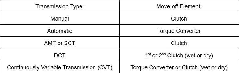
Figure 4: Transmission types and their corresponding move-off elements
While there are vastly different move-off elements depending on the transmission being used, all accomplish the same goal of helping move the supercar or hypercar from rest.
Getting a supercar or hypercar to move from standstill as quickly as possible is very important in terms of performance and driveability. In an effort to determine how effective the move-off element in a supercar or hypercar is, automotive engineers may calculate the slip associated with the move-off element. Below are a couple methods automotive engineers may use to calculate the move-off element’s slip:
S = (n_1-n_2)/n_1
S: Slip
n_1: speed of input shaft
n_2: speed of output shaft
S = 1 - 𝜂_C = 1 - 𝜈_C
𝜂_C: move-off element efficiency
𝜈_C: output/input shaft speed ratio
𝜈_C = n_2/n_1
As you can see, these formulas rely on efficiency between the input and output shafts. The higher the efficiency between these two shafts is, the lower the slip and the more power and torque can be applied to the supercar’s or hypercar’s drive wheels.
Once the car is in motion and gaining speed, automotive engineers must ensure that the transmission can securely hold onto the gear it's currently in until either the driver or TCM changes into another gear. The mechanism in the transmission which controls the gear in a multi-gear transmission being engaged and disengaged in this manner is called the master clutch component. Figure 2 shows the different master clutches in different transmission types:
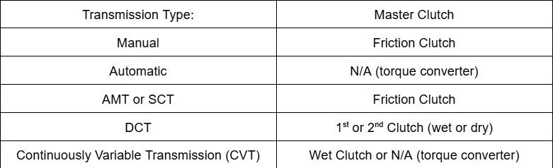
Figure 5: Transmission types and their corresponding master clutches
Similar to the move-off elements previously mentioned, the various master clutch types listed here serve the same purpose: to engage a selected gear until either the driver or the TCM wants the master clutch to disengage the gear to select another gear.
When the master clutch disengages from a gear in order for either the driver or the TCM to select another gear, the supercar’s or hypercar’s transmission will utilize the gear changing mechanism the automotive engineers designed and engineered for that transmission. Figure 3 shows a list of gear changing mechanisms for each transmission type:
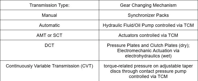
Figure 6: Transmission types and their corresponding gear changing mechanisms
The real outlier here is the CVT. It doesn’t use gears but rather adjustable taper discs which are connected to each other by either a polymer or metal chain belt. This allows for the transmission to adjust the input and output shaft speed based on the car’s speed without needing to change gears. This reduces impulse and allows for smoother operation.
Regardless, these transmissions are regulated through either robust gear changing or ratio adjusting mechanisms that allow for safe and reliable operation. Failure in this area can result in a damaged or completely compromised transmission which can result in safety concerns and thousands of dollars in damage, potentially totalling the supercar or hypercar. Therefore, it is of utmost importance for automotive engineers to accurately and precisely design and engineer these mechanisms in a supercar’s or hypercar’s transmission.
A Safe and Durable House
Since the transmission contains many moving parts spinning at high RPMs being lubricated by a specific volume of transmission fluid, the transmission housing containing all these parts must be able to withstand these forces. Automotive engineers must ensure the housing is made from the right amount of the right material to ensure optimal transmission performance and longevity. One way automotive engineers may confidently engineer and design a durable transmission housing is by utilizing a concept known as factor of safety (F.S.).
F.S. measures how much force an object can withstand compared to how much force the object will experience under normal operating conditions. Here is a formula to accurately determine F.S.:
F.S. = 𝜇_ult/𝜇_allow
F.S.: Factor of Safety
𝜇_ult: Ultimate Strength (lbs or N)
𝜇_allow: Allowable Strength (lbs or N)
As you can see, the object’s ultimate strength—the maximum force of the object—is divided by the allowable strength—the expected force under normal operating conditions—to yield a result. Depending on the budget and other factors, an S.F. value of 1.2 or greater is sufficient. An S.F. value of 1 or less must be avoided and should be corrected by the automotive engineers responsible for the transmission housing.
Different Combinations Toward the Same Goal
Now that we have an understanding of the basic transmission components and how they operate, we can discuss in further detail the different transmission types and how different components within them interact with each other. Why do so many driving enthusiasts prefer manual transmissions? How are automatic transmissions so reliable and efficient? How did SCTs and DCTs become the transmission of choice for supercar and hypercar makers? Why do only some cars utilize CVTs while others don’t? We’ll explore these topics and more in the following sections.
Grabbing Control of the Power
In the early years of the automobile and many years after the first mass-produced automatic transmissions were available, most cars were made with manual transmissions. These transmissions are where the move-off element, the master clutch and the gear changing mechanism are all engaged by the driver. Compared to automatic and other transmission types, these transmissions were simple to make due to their straightforward manufacturing and design process along with the fact that they don’t require a TCM to regulate gear changes.
In supercars and hypercars with manual transmissions, the move-off element consists of a friction clutch to help it engage with the engine. This works by having the friction plate within the clutch assembly slowly engage with the engine’s flywheel until the friction plate makes full contact with the engine’s flywheel smoothly and safely. This is accomplished by the driver slowly releasing the clutch pedal and slowly pressing the gas pedal simultaneously when the driver is in first gear. Below is Figure 10.2 from Automotive Transmissions: Fundamentals, Selection, Design, and Application by Harald Naunheimer et. al. showing this phenomenon in greater detail:
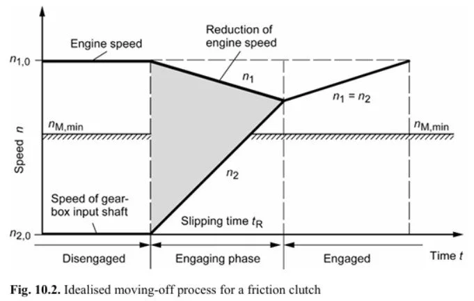
Figure 7: Move-off process diagram (Naunheimer p. 372)
Figure 7: Move-off process diagram (Naunheimer p. 372)
In Naunheimer’s figure, n_1 represents the engine or flywheel speed while n_2 represents the input shaft speed which is connected to the manual transmission’s friction plate. The engine speed is determined by how much force the driver applies to the gas pedal. This in turn determines when and at what engine RPM the driver will shift from first gear to second gear.
During takeoff in supercars and hypercars with manual transmissions, the engine’s RPM will decrease slightly as the friction plate from the transmission slowly engages and makes full contact with the engine’s flywheel. This is seen in the “Engagement phase” in Naunheimer’s Figure 10.2. Once the friction plate is fully engaged and makes full contact with the engine’s flywheel, both n1 and n2 are in sync. From there, the driver can disengage the friction plate from the engine’s flywheel by pressing the clutch pedal and selecting the next appropriate gear when the engine’s RPM and input shaft speed are just right.
If you notice in the figure, there is a moment at the end of the “Engaged” phase where n1 and n2 reach a maximum. This point reflects a moment when the load between the engine and the transmission occurs at the engine’s optimal speed based on the driver’s gas pedal input and driving conditions. Those with experience can sense this point in a car and manually shift between gears without disengaging the friction plate in an act known as “power shifting”.
Even though power shifting is possible, it is important to provide this warning statement to anyone willing to try this maneuver on their terms:
ONLY HEAVILY EXPERIENCED MECHANICS OR THOSE WITH EXTENSIVE TRANSMISSION AND DRIVETRAIN EXPERIENCE ARE ABLE TO PERFORM THIS MANEUVER WELL WITHOUT RUINING THE TRANSMISSION!!!!!! IMPROPER TECHNIQUE IN POWER SHIFTING CAN CAUSE TOTAL FAILURE OF THE TRANSMISSION, RESULTING IN CONSIDERABLE COSTS TO REPLACE TRANSMISSION OR MAY RESULT IN CAR BECOMING A TOTAL LOSS!!!!!!! THIS MANEUVER IS NOT ADVISED FOR THOSE WHO DO NOT HAVE EXTENSIVE TRAINING OR ARE NOT TRAINED MECHANICS AND ARE HEAVILY ENCOURAGED AND ADVISED TO NOT PERFORM THIS MANEUVER!!!!!!!!!
Here is more information on what power shifting is and how it’s generally not recommended from Engineering Explained’s Jason Fenske.
Whether or not you use the clutch pedal to engage and disengage the friction plate from the engine’s flywheel—again, strongly discouraged to not use the clutch pedal in manual transmission operations—doesn’t mean that the friction clutch isn’t being utilized at all. In fact, the friction clutch is the master clutch in manual transmissions which also engages and disengages selected gears.
The friction clutch accomplishes this by using clamping force to press onto the gear and hold onto it while the car is in operation. Clamping forces in manual transmissions are a result of the normal force—a force that’s exerted from one object perpendicularly to another object—pressing onto a gear due to a force from a spring. Here are two equations which model this behavior:
F_s = 𝜇_s * N
F_s: Force of static friction (lbs or N)
𝜇_s: coefficient of static friction
Varies by contact surface materials
N: Normal Force (lbs or N)
F_sp = -kx
F_sp: Force from spring (lbs or N)
k: Spring constant (lbs/in or N/cm)
Varies on type of spring
x: distance traveled by spring (in. or cm)
The normal force is used to create a force of static friction between the gear and the friction clutch. This static friction is what allows the friction clutch to hold onto the selected gear. The force of static friction is a direct result of the force from the spring. Notice how the first coefficient in the spring force equation is negative. That is because as the spring gets smaller, or compresses, the more force it exerts on other objects it comes in contact with. This is why manual transmissions in cars like supercars any hypercars use diaphragm springs in their friction clutches to help engage and disengage the selected gear (more heavy-duty vehicles like dual rear-wheel drive or “dully” trucks use coil springs instead to help engage and disengage different gears).
One challenge that automotive engineers had to face over the years with manual transmissions was the grinding that would result when gears were changed. However, an engineer by the name of Earl A. Thompson in the 1930’s helped discover synchronizer packs to solve this issue (he was also part of the engineering team at General Motors back in 1940 that invented the world’s first mass-produced automatic transmission, the HydraMatic, which still influences how automatic transmissions are designed and manufactured today). With synchronizer packs, the next gear being selected that is also acting as a freewheel—or a spinning wheel that is not engaged—can be in sync with the previously engaged spinning gear. The gear changing mechanism is so effective and is found in nearly all manual transmissions.
The Power of Hydraulics
As mentioned previously, Earl A. Thompson—the same person who led the development of synchronizer packs for manual transmissions—was also involved in helping develop the 1940 General Motors Hydra-Matic transmission that would go into select 1940’s Oldsmobile cars. It was such a success that other auto manufacturers followed and developed their own automatic transmissions. The Hydra-Matic was also so reliable and performed so well that it still influences how automatic transmissions are made today!
So, how do automatic transmissions work, exactly? Is it the same as a manual, except something else other than the driver is selecting the different gears? What makes an automatic transmission shift, exactly? Let’s go ahead and answer these questions and more
Yes, the automatic transmission does, in fact, shift on its own without any input from the driver. However, automatic transmissions are not linear designs in the sense that there are individual gear pairs for 1st gear, 2nd gear, 3rd gear, 4th gear, and so on in them as in a manual transmission. Also, the move-off element in automatic transmission is not a friction plate like what’s used in a manual transmission. Furthermore, the mechanism which holds onto the gear is not just one clutch but a series of clutches. It’s safe to say that there are many more differences between automatics and manuals than just one requires the driver to manually select the gears and the other does so automatically.
For supercars and hypercars with automatic transmissions, the move-off element is known as a torque converter. This mechanism is usually made up of four different components: a torque converter clutch, an impeller or “pump”, a turbine, and a reactor or stator. The torque converter clutch is the component which makes contact with the engine’s flywheel in a similar manner that a manual transmission’s friction plate would. The torque converter’s impeller or “pump” flings automatic transmission fluid (ATF) to the torque converter’s turbine. The turbine then uses the ATF to help turn the automatic transmission’s input shaft. To keep the process going, the torque converter’s reactor or stator redirects the ATF towards the impeller.
Notice how the torque converter uses an impeller and a turbine to move the input shaft. This explains why cars with automatic transmissions move at idle when the car’s engine is in operation. The small amount of rotation by the automatic transmission’s torque converter via its impeller and turbine even without any input from the driver causes the car to move ever so slightly.
The torque converter clutch used to engage with the engine’s flywheel is also used as the car’s master clutch to engage with the selected gear. This is similar to how friction clutches in manual transmissions are used for both engaging with the engine’s flywheel and also with the gear the driver selected. This is why you can really feel the gear changes in cars with less refined automatic transmissions. Past this point is where automatic transmissions get complicated.
In automatic transmissions, the gear changing mechanism is not as straightforward as synchronizer packs in manual transmissions. It consists of various clutch shifting mechanisms inside the automatic transmission that are regulated by ATF. The ATF in the transmission that’s being used to change gears is regulated by the automatic transmission’s TCM and valve body. While we previously discussed what a TCM is, we haven’t yet discussed valve bodies for automatic transmissions.
What are valve bodies? Well, before electronics governed machine behavior, engineers used a series of valves and fluids to manipulate how machines would behave under user inputs and certain conditions. In the case of the 1940 Hydra-Matic transmission and other automatic transmissions afterward, engineers used what is known as a valve body using the transmission’s ATF to govern gear changes. Valve bodies are maze-like devices which use a series of valves and solenoids that respond to the varying ATF pressure inside the valve body. Based on meticulous and precise measurements, the solenoids and valves are activated in such a way that allows the transmission to shift on its own. Valve body design and repair is so detailed and involved that usually engineers and mechanics need to be specialized in transmissions or valve bodies in order to effectively work on these mechanisms.
The automatic transmission’s valve body activates various clutch shifting mechanisms inside the transmission to select the desired gear. These clutch shifting mechanisms include: a clutch to one-way clutch shift, a clutch to clutch shift, a reaction clutch, and a coupling clutch. The coupling clutch is used to select clutches in automatic transmissions which contain planetary gear trains.
What is a planetary gear train? Now, this is where automatic transmissions really differentiates themselves from manual transmissions. This gear train consists of a central gear called a sun gear surrounded by two or more planetary gears. These gears are then held together by an outer ring gear. Depending on how the planetary gear train is configured, this one planetary gear train assembly can consist of multiple gears. In more modern automatic transmissions, there may be two or three of these planetary gear trains. Just when you thought this was already complex, planetary gear trains can get even more complicated. Some have more than just one sun gear and can have varying planetary gears. They can even have what are known as carriers on planetary gears. From this alone, one can tell that no two automatic transmissions are always alike.
Figure 8: Planetary gear train diagrams (Zhang p. 104)
To help keep things in order, engineers may use what’s known as a clutch table. This is nothing more than a table of clutches and other shifting mechanisms in a given automatic transmission that shows which clutches and shifting mechanisms are being used to select a particular gear. Here is an example of a clutch table from Automotive Power Transmission Systems by Yi Zhang and Chris Mi:
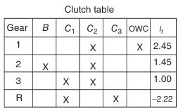
Figure 9: Clutch table showing which clutches are used to engage each respective gear in automatic transmission (Zhang p. 138)
Here is what each of the abbreviations means for the clutch table for this 3-speed automatic transmission:
I_t: Clutch ratios
B: Band Clutch
C_1: Multiple disc hydraulic clutch 1
C_2: Multiple disc hydraulic clutch 2
C_3: Multiple disc hydraulic clutch 3
OWC: One Way Clutch
Hopefully now it’s clear why automatic transmissions were considerably more expensive than manual transmissions and why engineers and people in auto repair who specialize in transmissions are able to manufacture and maintain automatic transmissions. While efficient and reliable, they are incredibly complex mechanical devices. Thankfully, advancements in automotive engineering have allowed OEMs to use simpler transmission types that can also change gears or adjust output shaft speeds with little to no effort from the driver.
Returning to the Basics?
Although automatic transmissions made life easier for millions of drivers through reliable hands-free shifting, there were downsides to these transmissions in the beginning. One was the obvious challenge of manufacturing such a complex transmission at a mass-scale, driving up costs for consumers. Another was the repairs which certain mechanics refused to do because automatic transmissions were so complex and varied from one another. In terms of this article’s focus—transmissions and drivetrains in supercars and hypercars—these transmissions just couldn’t keep up with the performance demands that were expected of supercars and hypercars.
Fortunately, however, engineers were able to create a solution to the problem of easy fast shifting. This was first revealed in the 1997 Ferrari F355 as an optional upgrade and was an instant hit. This solution is now known as either an automated manual transmission (AMT) or a single-clutch transmission (SCT). Just to illustrate how effective this transmission is, cars such as the Ferrari Enzo used it to deliver optimal high speed performance for both experienced racecar drivers and novices alike—albeit at a steep cost of approximately $600,000 USD (or over $1,000,000 in 2026 dollars) to experience the Ferrari Enzo and its amazing SCT!
What is a SCT and why is it so special, especially back in 2003? SCTs are automated manual transmissions. To break it down more plainly, these transmissions are just like manual transmissions in terms of their mechanical operation. They use a friction plate as their move-off element, a friction clutch as their master clutch and synchronizer packs as their gear changing mechanism.
So, what’s the difference between AMTs/SCTs and traditional manual transmissions? It’s the fact that AMTs/SCTs use actuators to engage and disengage the clutch from takeoff and also desired gears during operation. There are two main types of actuators in AMTs/SCTs: hydromechanical actuators and hydroelectrical actuators. An OEM might select one type of actuator over the other based on vehicle needs, performance targets, and operational budget.
As discussed in the introduction, SCT transmissions have very short shifting times due to their build and the electric components used in their manufacturing like a TCM. As a result, automakers have been able to get shifting times in certain supercars such as the Lamborghini Aventador in as little as 50 milliseconds. This is quicker than an average person driving a car with a manual transmission can shift and certainly much faster than certain automatic transmissions can shift. What’s even more interesting is that, depending on the supercar’s or hypercar’s intended function, the gear selector can be paddle shifters located on the steering wheel directly behind the 3 ‘o clock and 9 ‘o clock positions, a shifting stick, or nothing at all.
However, cars with SCTs usually have less refined shifts. This is why cars such as luxury cars still use automatic transmissions rather than SCTs. Moreover, it is also a reason why certain sports cars might feel less refined to drive compared to luxury cars. Nonetheless, these transmissions were able to allow drivers from all skill levels to enjoy the supercars of their era and safely push them to their limits. This was the case until a new type of transmission came onto the scene.
Doubling Down on the Fundamentals
If the SCT transmission wasn’t quick enough, then just wait until you hear about the dual-clutch transmission (DCT). As the name suggests, there are two clutches present rather than one. One way to think of DCTs is that they are basically two SCTs or traditional manual transmissions in one transmission housing. Rather than one input or output shaft for all the gear pairs in the transmission, DCTs utilize two input shafts and two output shafts. One set of gear pairs utilize one shaft and the other gear pairs utilize the other shaft. The two shafts may be made as one assembly unit where one shaft may be inside of the other hollow shaft.
Besides the two input and output shafts and two clutches, DCTs and SCTs operate very much the same way. The move-off elements and master clutches in DCTs are either one of the two friction plates as found in “dry” DCTs or multiple wet clutches as found in “wet” DCTs. The difference between “dry” DCTs and “wet” DCTs is the use of oil in the transmission. High performance cars use the oil in “wet” DCTs as a means of heat dissipation and is why it can be found in Hyundai’s N performance series cars. This is similar to the idea of using a dry sump system in high performance engines as discussed in the “Behind the Mechanical Heartbeat” section of Old School Heart with New School Brains.
Both “dry” and “wet” DCTs use synchronizer packs for their gear changing mechanisms, but utilize them differently. In “dry” DCTs, actuators like those seen in SCTs are used to change gears and electric “dry” DCTs use electric motors to change gears. In “wet” DCTs, however, a mechanism which engages the ongoing clutch and disengages the outgoing clutch that’s similar to what’s seen with clutch to clutch gear shifts in certain automatic transmissions is used to help change gears.
Smooth and Seamless Change
Even though supercars and hypercars mainly utilize DCTs these days, the next transmission is not nearly as prevalent in high performance circles, but it is still a major transmission design in automotive engineering. These transmissions are known as continuously-variable transmissions (CVTs). Since CVTs aren’t really present in supercars and hypercars, this article will discuss these transmissions with enough detail for you to understand how they operate and why they work so well in select automobiles.
CVTs use either a wet clutch, a dry clutch, or a torque converter as their move-off element. It all depends on how the CVT was manufactured. In terms of their master clutch, they may use a wet clutch, dry clutch, or a torque converter clutch similar to what’s found in ATs. Again, this is reliant upon how these transmissions are manufactured.
Where CVTs are unique is in the fact that there aren’t any gears in their transmissions. Instead, these transmissions adjust their input shaft/output shaft speed ratios by adjusting each pulley that is on either the input shaft or the output shaft. The pulleys are connected to each other via either a metallic or strong polymer band. Pressure from the transmission fluid along with the CVT’s TCM moves both pulleys which, in turn, adjust the input/output shaft ratios while the band holding the two pulleys remains in place.
Since the input/output shaft ratio changes are seamless thanks to this unique design, these transmissions are mainly found in cars designed to maximize fuel efficiency and handle regular driving loads. Supercars and hypercars which have redlines of 8,000 to 10,000 RPMs need robust transmissions like SCTs or DCTs which are designed with high-strength materials such as aluminum and steel and have tight tolerances for limited to no slip. Placing a CVT in such a high-powered, high-performance car may negatively affect longevity and performance, especially if the CVT is not able to handle such power from the engine.
Useful Power Brokers
Regardless of which type of transmission is used in the supercar or hypercar, one thing is for certain: the transmission’s goal is to transmit power to the drive wheel(s) through a drive shaft or drive shafts and a final drive assembly or final drive assemblies. Without these crucial pieces, cars with internal combustion engines (ICEs) and one of the transmissions that were explored previously would not be able to sufficiently and reliably provide power to the drive wheels. How, then, do the drive shaft(s) and the final drive assembly/assemblies work? Let’s explore these components together.
From the transmission, the output shaft is directly connected to the car’s driveshaft. While it’s nothing more than a simple metal rod in terms of the way it’s manufactured, this rotating rod is critical to the way the car operates. The role of this mechanism is to transmit power from the output shaft of the car’s transmission to the car’s final drive assembly/assemblies. This is accomplished by utilizing universal joints, or Hooke joints, to each end of the drive shaft(s), allowing it or them to connect to the transmission’s output shaft and the car’s final drive assembly/assemblies. This design is also used to aid in the flexibility of the driveline’s assembly and also greater driveline flexibility overall, which can be important for any future service work the car might need.
This manufacturing process, however, can potentially add more weight to the vehicle and require more available space from the vehicle. In vehicles that are very dependent on weight and space configurations such as supercars and hypercars, this can lead to lost performance and a decrease in efficient energy consumption. Thankfully, the automotive engineers behind modern-day supercars and hypercars utilize specialized axles which connect directly to the vehicle’s transmission to reduce weight and save space. These axles are called constant velocity (CV) axles.
These axles use either a half axle or haft axle, depending on the book you study from. Each half or haft axle is connected to an outer CV joint and an inner CV joint. The outer CV joint connects to the supercar’s or hypercar’s drive wheels. The inner CV joint connects to the supercar’s or hypercar’s transmission. Supercars and hypercars which utilize this setup have the final drive assembly/assemblies inside the transmission housing and are called transaxles, which allow for more direct power transfer. Here is some more good information on CV axles if you’re still interested.
Regardless if the car utilizes CV axles or not, all cars are equipped with mechanisms known as differentials. These are mechanisms which transmit torque from either the car’s output shaft in transaxle cars or drive shaft in other cars to the car’s drive axle. The drive axle in supercars and hypercars is usually in the rear and is a CV axle due to their independent rear suspensions that allow for greater handling. Many American muscle cars, however, use solid rear axles as drive axles since many of them were built mainly for straight-line performance.
One type of differential used in supercars and hypercars is what’s known as a limited-slip differential. As mentioned before when discussing each transmission’s move-off element in “The Elements of Change” section, slip must be managed to efficiently provide power to the driving wheels. With a limited-slip differential, the mechanism shifts a portion of the torque to the wheel with most traction and limits the slip in the wheel with least traction. This reduces power loss, which is especially useful in environments where the road surface may not produce enough traction with the drive wheel’s tire, including roads covered in fine sand and soil or pockets of water. Newer models like in newer Ford models use electronic limited-slip differentials which are regulated by sensors that monitor the rotation speeds of the drive wheels.
Inside the differential lies the component which makes the differential special: the final drive assembly. This is either a collection of spiral bevel or hypoid gears in the differential which multiply torque from either the drive shaft or the output shaft by a final drive ratio iE. The iE is the ratio which informs the driver by how much the torque from the car’s drive shaft or output shaft will be multiplied by per one unit of torque. The car’s iE is determined by the automotive engineers designing and engineering the supercar or hypercar and is based on the performance metrics the OEM wants the supercar or hypercar to achieve. Many OEMs aim to have the iE for the supercar or hypercar they are designing and engineering to be somewhere between 2.5:1 or 4:1—which is the ideal range for supercars and hypercars.
Once the iE for the supercar or hypercar is set, the engineers in charge of the drivetrain may ask this question: should the differential be placed in the front, the rear, or on both axles? Which one will return the greatest amount of performance per unit of power and torque? The answer might surprise you.
If the automotive engineers place the differential or transaxle on the front axle only, then the car’s drivetrain would be considered a front-wheel drive (FWD) configuration. This configuration type is not common among supercars and hypercars, but is common among high-performance versions of everyday cars. One powerful example of a high-performing FWD car would be the Honda Civic Type R.
More often than not, supercars and hypercars have their differentials or transaxles placed on the rear axle only. This type of setup is known as a rear-wheel drive (RWD) configuration. Examples of RWD supercars and hypercars include the Chevrolet Corvette ZR1, the Porsche 911 GT3 RS, and the Ford Mustang GTD.
More so than before, OEMs producing supercars and hypercars are either creating differentials and transaxles on both axles or creating a transaxle or differential on one wheel and having an electric motor power the other axle. In either setup, both the front and rear axles of the car are the driving wheels. These cars are known as all-wheel drive (AWD) vehicles. Supercars and hypercars which utilize an AWD system of some kind include the legendary 2009 Nissan GTR (R35), the McLaren W1, the Chevrolet Corvette ZR1X, and the Ferrari F80.
Magnetically Electrifying
While supercars and hypercars still mainly utilize ICEs or hybrid powertrains, a growing number of supercars and hypercars are using electric motors to bring about the ultimate performance. To give you an idea how automotive engineers use electric motors, check out the “A New Power Source” and “A Stable Motoring Force” subsections in Unifunful’s article Old School Heart with New School Brains.
In the article, supercar and hypercar OEMs use PM BLDC electric motors to provide instantaneous torque along with a lithium-based battery as an energy source. These motors can be placed on either the front axle, rear axle or both axles, making the supercar or hypercar FWD, RWD or AWD, respectively. Even though electric vehicles (EVs) usually weigh more than their ICE-powered counterparts, they usually provide more instantaneous off-the-line performance due to the instantaneous torque the electric motor(s) provide.
Adequate Power Throughout
Regardless if a supercar or hypercar has either an electric motor or an ICE powerplant, it is important to see if the car is able to convert most of the power from the powerplant to the driving wheels. While supercar and hypercar OEMs do their best to minimize power losses by making all the parts in the drivetrain as light as possible while ensuring the moving parts are adequately lubricated and have the tightest tolerances to prevent unnecessary friction and slip, losses still happen in the drivetrain. Furthermore, this can be a cumbersome task to determine where the power losses are coming from within the drivetrain. Thankfully, engineers have at least a couple tools they can use to determine how efficient the drivetrain is at retaining power from the supercar’s or hypercar’s powertrain to the drivewheels.
Both of the tools this section will discuss measure something known as the car’s powertrain ratio. The powertrain ratio can be defined as a method used to see how much of the power from the engine is converted to the supercar’s or hypercar’s driving wheels. Below are a couple tools in the form of formulas which help determine the powertrain ratio:
i_A = i_S * i_G * i_E
i_A: Powertrain ratio
i_S: Ratio of the moving-off element
i_G: Transmission ratio
i_E: Final Drive Ratio
While also another powertrain ratio formula, the next one can be used to determine the max powertrain ratio:
i_A, max = (r_dyn * m_F * g * ((F_rr * cos (𝛼_Sl)) + sin (𝛼_Sl))) / (T_M, Max * 𝜂_tot)
i_A, max: maximum powertrain ratio (stall torque ratio)
r_dyn: dynamic tire radius
m_F: vehicle mass
g: Earth’s gravitational pull (9.81 m/s^2 or 32.2 ft/s^2)
F_rr: rolling resistance from wheels and tires
F_rr = C_rr * N
C_rr: rolling resistance coefficient
Usually between 0.001 or 0.0015 for cars
N: Normal force (lbs or N)
𝛼_Sl: slope angle
T_M, Max: total engine torque
𝜂_tot: total drivetrain system efficiency
Even though both can be used to determine the powertrain ratio in a supercar or a hypercar, the methods behind both are very different. One is a more straightforward approach measuring different components of the drivetrain itself while another is used to see where power is being used or lost both inside and outside the drivetrain. Nonetheless, both can be useful when determining drivetrain efficiency.
As discussed briefly early on in this section, energy loss can be attributed to friction. While lubrication greatly reduces friction, there is still some energy loss in the drivetrain due to friction in the form of heat. Here is another tool automotive engineers can use to determine energy loss due to the heat in the drivetrain caused by friction:
W = ½ * ( -J_red, i * Δ⍵_i^(2) -T_V * Δ⍵_i * t_R)
W: Work as a result of friction (heat) (Joules)
J_red, i: Reduced polar moment of inertia for idler (ft4 or m4)
See the polar moment of inertia explanation in
The Art of Mastering Driving for more information
⍵_i: Angular velocity of idler (rad/s)
T_V: Input shaft torque (N * m or lb-ft)
t_R: Slipping time (s)
Having a tool such as this equation along with the two powertrain ratio equations can make life so much easier for automotive engineers. That way, supercars and hypercars can be engineered more accurately and thoroughly to maximize performance and minimize powertrain losses.
The Price of Precision
As with most things in life, all things come at a cost, and sophisticated drivetrains are no exception to this reality. One factor in the drivetrain cost comes from the complexity of the drivetrain itself. For example, automatics have always cost more than manuals due to their more complex design. DCTs cost more than SCTs since there are two friction clutches, hollow shafts, and two sub gearboxes whereas an SCT is essentially an electronic manual transmission.
Another factor when it comes to cost is which materials are used to manufacture these different components. Components which might not require as much durability with heat and friction but still require to be very strong might be made from materials such as woven carbon fiber. Components which do require strength, durability and heat resistance might be made from forged metals like forged aluminum or specific metal alloys such as aluminum alloy. Such materials drastically increase the cost of the drivetrain.
Furthermore, manufacturing costs will also influence the overall cost of the supercar’s or hypercar’s drivetrain. Drivetrain components that are complex and made from select materials might be harder to manufacture, leading to increased labor costs. Also, when it comes to drivetrains in supercars and hypercars, tolerances must be tight to minimize powertrain losses, leading to sophisticated manufacturing techniques, which also drive up costs.
So, what methods can automotive engineers use to help determine these costs? Well, it turns out that automotive engineers can apply economics to the situation. This isn’t in the traditional sense of a classically trained economist surveying the project and outlining every single action that will lead to a profit or a loss. Instead, automotive engineers may utilize knowledge from what’s known as engineering economics. Let’s explore how engineering economics is used and applied.
When creating a drivetrain, automotive engineers may consider these various costs:
Fixed Cost (FC)
Costs that are constant and do not depend on output or how much activity the plant produces
May include buildings/New Construction, Equipment, Property Taxes,
Licence or fees
Variable Cost (VC)
Costs that rise and fall depending on how much the company produces
May include Labor, utilities, maintenance & repairs, materials and
supplies
Average Costs
The total cost to produce a product divided by the number of units produced
Used to determine the price of each produced unit
Opportunity Cost
Costs associated with a once available product or service opportunity
that is no longer an opportunity the company can pursue
Might be evaluated against costs with a current product or service
the company produces
Sunk Costs
Costs which the company has paid for in the past and do not apply to the
product or service itself
Old equipment, materials for another product, resources for another
product or service
Incremental Costs
Comparison of costs between one product or service to another product or
service
Furthermore, automotive engineers may consider these economic analysis tools:
Break-even point
When the total revenue (TR) of operations equals the total costs (TC) to run operations
TC = TR
TR = SP * Q
SP: Selling Price of Product
Q: Quantity of Product
TC = FC + TVC
FC: Fixed Costs
TVC: Total Variable Costs
TVC = VC * Q
VC: Variable Costs
Q: Quantity of product
Automotive engineers may also assess the drivetrain’s life cycle. This is a process where the summation of all costs and revenues generated from the whole life cycle of a particular product or design are calculated. Here are some things automotive engineers consider during the life cycle cost process:
tooling
labor
utilities
infrastructure
revenues
While automotive engineers are determining those costs, they are also determining the answers to questions like these:
When will this product or service begin to generate a profit for the
company and how can we maximize this product’s or service’s
profit?
When will this product or service eventually begin to cost the
company more money to produce than to sell? Should the
company improve the product or create a whole new product
instead?
This question also ties into cost-benefit analysis in terms of automotive
engineering
Automotive engineers may also be tasked to calculate the overhead costs—the costs associated with running the business without directly being involved in creating products or services like Human Resources, administrative costs, maintenance crew—and minimum cost—the lowest possible cost to produce a product or service which are at the company’s disposal.
As with any business, time is money in the automotive industry. Depending on how much time it takes to engineer and manufacture a drivetrain determines how much money they can allocate to other projects and investments. Thankfully, engineers when using engineering economics can utilize a concept called Time Value of Money. This concept is based on the idea that the value of money itself and what it can buy (purchasing power) or what it can be used for (money as an asset) and how much it can earn for a company (return on investment) or a bank/financial institution (interest on a loan) changes throughout time. Below are just some of the ways automotive engineers may use the concept of Time Value of Money when determining how much it will cost to create a sophisticated drivetrain for a supercar or hypercar:
Simple Interest
An F future sum calculation which is collected at the end of n number of years at i interest on P present sum
F = P + (P * i * n)
Compound Interest
An F future sum calculation where interest i is compounded onto
the present sum within a particular schedule (yearly, quarterly or every three months, monthly, etc.) for n number of compounding cycles
Common interest practice
Single Payment Compound Interest
The Amount of money accumulated at a designated interest rate over a compounding time period in years which could be compounded every month, quarter, or year
F = P(1 + i)^n
F: Future sum of money
P: Present sum of money
i: interest rate
n: number of compounding periods
F/P: Multiplier used to determine present sum’s future sum
value based on interest rate and compounding cycle
F = P * (F/P, i, n)
Whatever the F/P value is at i interest rate
for n number of compounding periods is
how much the present sum is multiplied by
Equivalence
Using different payments or investments made at different periods
of time to arrive at a single value now, annually, or at a predetermined date in the future
Single Payment Present Worth
A calculation on present sum P of money based on future sum F target using a designated interest rate i over a compounding time period in years which could be compounded every month, quarter, or year (n)
P = F(1+i)^(-n)
P = F * (P/F, i, n)
Whatever the P/F value is at i interest rate
for n number of compounding periods is
how much the future sum is multiplied by
Uniform Series calculations:
Compound Amount Factor
F = A * (((1 + i)^(n) - 1) / i)
F: Future sum
A: annual investment or payment
i: interest rate
n: number of compounding periods
F = A * (F/A, i, n)
Whatever the F/A value is at i interest rate
for n number of compounding periods is
how much the future sum is multiplied by
Sinking Fund Factor
A = F * (1/((1+i)^(n) -1))
A = F * (A/F, i, n)
Whatever the A/F value is at i interest rate
for n number of compounding periods is
how much the annual payment is multiplied by
Capital Recovery Factor
A = P * ((i * (1+i)^(n))/((1+i)^(n) -1))
A: Annual return
P: Present Sum
i: interest rate
n: number of compounding periods
A = P * (A/P, i, n)
Whatever the A/P value is at i interest rate
for n number of compounding periods is
how much the present sum is multiplied by
Present Worth Factor
P = A * (((1+i)^(n) -1)/(i * (1+i)^(n)))
P = A * (P/A, i, n)
Whatever the P/A value is at i interest rate
for n number of compounding periods is
how much the annual return is multiplied by
It’s important to note that All Uniform Series calculations are used by companies to determine the product’s or service’s internal rate of return (IRR), or how much revenue the product or service will generate on an annual basis. The IRR on a project is the discount rate that makes the net present value of all cash flows (i.e. inflows and outflows) equal zero based on its discounted cash flow (DCF), or cash flows for the whole life cycle of the product or service.
The Final Review
Hopefully by now you understand why transmissions and drivetrains are a vital part of supercars and hypercars. They greatly influence fuel efficiency, power delivery to the drive wheels, and how well the supercar or hypercar handles. Without them, supercars and hypercars wouldn’t deliver the same driving experience they already do.
Furthermore, as governments and societies around the world are placing more pressure on OEMs to make more fuel efficient and environmentally friendly vehicles, optimizing drivetrains to maximize efficiency and minimize energy losses and fuel consumption is a must. This is why auto manufacturers are developing 10-speed automatic transmissions and more CVTs for their vehicles. The challenge for supercars and hypercars of the future is to not only meet these demands from societies and governments but also to ensure the driving experience isn’t diluted.
Before you go, here are some questions that you can ponder on:
How are some ways automakers can make this into a reality?
What are some methods automakers are not currently using that can make these goals a possibility?
What are your thoughts on the future importance of transmissions and drivetrains?
Let us know what you think in the comments!
Additional References:
Harald Naunheimer, Bernd Bertsche, Joachim Ryborz, and Wolfgang Novak . Automotive Transmissions: Fundamentals, Selection, Design and Application, Second Edition. Springer-Verlag Berlin Heidelberg, 2011.
Yi Zhang and Chris Mi. Automotive Power Transmission Systems. John Wiley & Sons, Ltd., 2018.
Erik Oberg, Franklin D. Jones, Holbrook L. Horton, Henry H. Ryffel, and Christopher J. McCauley. Machinery’s Handbook, 31st Edition. Industrial Press, Inc., 2020.
Get a quick dose of inspiration from Unifunful Today here
See our thought-provoking articles from Everyday Engineering here and investigate the engineering behind everyday items and places
See more articles from Engineering in Motion here to see how engineering moves us around the world
Missed last week? No worries, we got you! See what we covered last week and more in our weekly status reports here
Discover the vision and values guiding the Unifunful mission here
First time visiting Unifunful? Become familiar with the history and foundation Unifunful was built on here
Meet the contributors who make Unifunful possible here