

The Art of Mastering Driving
From the very beginning, mankind has been interested in speed and getting places quicker and more efficiently. For many years, this was accomplished on land by horses. Not only are they elegant and beautiful creatures, but they are also nimble, agile, and able to either go long distances or make short, powerful sprints. They could also haul large quantities of goods for long distance trips across places like the American West as Americans moved westward.
However, as technology and society evolved, so did humanity’s need for more efficient and reliable transportation. In the late nineteenth century and early twentieth century, only a handful of Americans could even afford an automobile. The first automobile sold in America was made by Winton Motor Carriage Co. and was sold for $1,000 to a man named Robert Allison from Port Carbon, PA, which is just outside Pottsville, PA. Beginning on page 332 of this document from the Department of Labor, you can see that at most a person’s daily wage in 1899 was near $5.00 a day. Since Americans in 1899 worked on average 6 days a week, this amounted to around $1,500 per year, which meant two thirds of this person’s yearly wage went towards purchasing a car.
However, these wages were mainly for foremen, which was a position that required experience, skills, and qualifications like leadership abilities. Getting a degree was only for the rich in those days and, according to pages 16 through 18 of this document from the National Center for Education Statistics, most people never went to college and only a little over half of the population were enrolled in a school of some kind. Due to these circumstances, most people worked jobs that paid only $1.00 to $2.00 a day in 1899. Simply put: most of these folks couldn’t afford such a vehicle.
This changed in 1908 when the Ford Model T was introduced to the world, but the pursuit of finding ways of quicker transportation and greater speed didn’t stop with the Model T. Many say the first sports car was the 1914 Vauxhaul 25 horsepower (hp) ‘Prince Henry’ Sports Torpedo. Many point to other cars that pushed the boundaries of speed and performance during this time. Regardless of who came first, these cars showed just how focused people were to enhance and improve the sports car.
In 1954, Mercedes-Benz pushed the envelope and made a breakthrough in sports car design and engineering that changed the world forever: The Mercedes-Benz 300 SL Gullwing, which is arguably the world’s first supercar. With its 215 kW, or 288 hp, straight-6 cylinder engine, its unique design, and iconic gull-wing doors, the 300 SL Gullwing was able to reach a top speed of 250 km/h, or 155 mph. In 1954, this was a monumental feat of engineering and made it the fastest car in the world.

Mercedes-Benz 300 SL Gullwing (Image courtesy of Mercedes-Benz)
Fast-forward twelve years and the supercar evolved with the Lamborghini Miura. The major advancements here are the car becoming mid-engined and incorporating a more aerodynamic shape. These enhancements, along with its 350 hp V-12 engine, managed to propel the car to a top speed of 280 km/h, or 174 mph, and reach 0 to 100 km/h in 6.7 seconds, making it the fastest car in the world at the time.

Lamborghini Miura (Image courtesy of Automobili Lamborghini S.p.A.)
Ferrari answered Lamborghini with the 1974 Ferrari 365 GT4 BB. With its 4400 cubic centimeter V-12 engine that produced 380 hp, its sleek body, and one of the first cars to incorporate a monocoque chassis, the 365 GT4 BB achieved a top speed of 300 km/h, or over 186 mph. This cemented the 365 GT4 BB as the world’s fastest car.
Lamborghini again upped the ante by creating the 1974 LP 400 Lamborghini Countach. Though it didn’t break speed records, what it did was push the boundaries of design for supercars and its influence can still be seen today. It still wasn’t a slouch, especially with its 4 Liter V-12 engine that produced a healthy 375 hp.

Lamborghini Countach (Image courtesy of Automobili Lamborghini S.p.A.)
As the late 1980s approached and the 1990s were around the corner, the 200 mph mark was becoming an inevitability. This was especially true with the arrival of the 1986 Porsche 959, a car that shattered speed and acceleration records. With its sequential twin-turbo 2849 cc 444 hp rear-mounted flat-six engine, along with its iconic silhouette and aerodynamic elements, the 959 was able to reach a top speed of 320 km/h, or almost 199 mph and was the fastest production car in the world. Furthermore, due to its powerful engine and smooth transmission, the 959 was able to accelerate from 0 to 60 mph in just 3.7 seconds.

Porsche 959 (Image courtesy of Dr. Ing. h.c. F. Porsche AG)
Ferrari also had a special car in the works as well, which would be known as the Ferrari F40. Even though the 1987 Ferrari F40 had almost the same acceleration that the Porsche 959 did, it managed to break through the 200 mph barrier, posting a top speed of 324 km/h, or just over 201 mph and claiming the crown as the world’s fastest production car. It was able to achieve this feat by its 2936.25 cc 478 hp twin-turbo V-8 along with its own aerodynamic elements to help the car move through the air.

Ferrari F40 (Image courtesy of Ferrari S.p.A.)
The 959 and the F40 maintained their place atop the supercar realm until another car would emerge from the U.K. and turn the automotive world upside down again. It would come from a manufacturer based in Woking, England by the name McLaren with their groundbreaking model: the 1992 McLaren F1. It was able to reach 240+ mph and it was able to accelerate from 0-60 mph in 3.2 seconds. It featured a 6.1 L BMW 627 hp, a smooth shifting six-speed manual transmission, a carbon fiber monocoque chassis, and a three-passenger cabin with the driver sitting in the middle that not only helped the McLaren F1 achieve these benchmarks, but also made the world’s fastest production car into an ultra-exclusive daily driver.

McLaren F1 (Image courtesy of McLaren Automotive)
As the McLaren reigned supreme throughout the 90s and early 2000s, Ferrari decided to take a different approach to the supercar with its next two models: the Ferrari F50 and the Ferrari Enzo. While these cars never claimed the crown of the world’s fastest production car, they still set benchmarks for performance and supercar engineering. The Ferrari F50 was the world’s first production car made with a pushrod suspension, similar to the ones seen on F1 racing cars. The Ferrari Enzo further refined this technology and made it to where it could be used on roads more effectively.

Ferrari Enzo (Image courtesy of Ferrari S.p.A.)
Of course, the F50 and the Enzo held their own when it came to performance. The F50 still had a 0-60 time of 3.87 seconds and a top speed of 325 km/h, or almost 202 mph thanks to its 520 hp V-12 engine. The Enzo surpassed these performance benchmarks by recording a 0-60 time of only 3.65 seconds and a top speed of over 350 km/h, or over 217 mph thanks to its 660 hp V-12 engine.
By the mid 2000s, however, the supercar landscape was about to evolve and transform into a new echelon of performance that can only be described with the word “hypercar”. The car that made this happen? Look no further than the 2005 Bugatti Veyron. It was the first production car with over 1,000 horsepower (1,001 hp), could do 0-60 in under 2.5 seconds, and had a top speed of 407 km/h, or close to 253 mph, making it the fastest production car in the world at the time. It had a unique, Volkswagen sourced W-16 engine and was mated to a dual-clutch transmission that was able to produce incredibly quick shifts and an all-wheel drive system that was able to efficiently transfer all the power to all four wheels.

Bugatti Veyron (Image courtesy of Bugatti Automobiles S.A.S.)
However, as those famous European brands were shaping the way the world looks at performance, many outside Europe were beginning to challenge the way the global high performance landscape looks. Take, for example, the 2005 Ford GT, the 2009 Nissan GT-R, and the 2009 Chevrolet Corvette ZR1. Not only were these cars good, but they commanded respect from the likes of Porsche, Ferrari and Lamborghini.
When Ford released the GT back in 2005, it was a new direction for Ford as the 1960s GT40s, the car the 2005 Ford GT was based off of, were only made for the track and performed very well in races like Le Mans, where the 1966 Ford GT40 finished 1-2-3 at Le Mans that year. In any case, the 2005 GT was a serious high performance car that boasted a supercharged 5.4 L V-8 engine producing 550 hp. The GT’s engine, coupled with a smooth six-speed manual transmission along with its chassis, was able to reach 0-60 in 3.3 seconds, the quarter mile in 11.2 seconds, and achieve a top speed of 205 mph. It was so good that it not only won a Car and Driver comparison between the Ferrari Challenge Stradale and a Porsche 911 GT3, but was able to go head-to-head in a Motor Trend comparison test between the Porsche Carrera GT and the Ferrari Enzo.
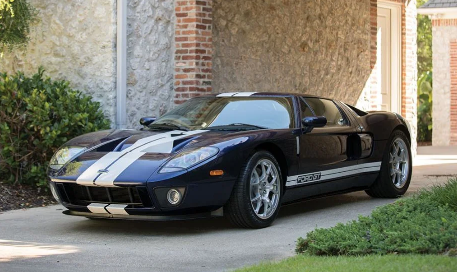
2005 Ford GT (Image courtesy of The Supercar Blog)
The Ford GT wasn’t the only one challenging European pure bloods, however. In 2009, Nissan introduced the GT-R and Chevrolet introduced the ZR1 variant of its C6 Corvette. Both Chevrolet and Nissan have been producing these cars for many years (the GT-R was called the Nissan Skyline GT-R, but the Skyline portion was dropped with the release of the R35 GT-R). What was different about this year was how the GT-R and the Corvette ZR1 both were able to not only hold their own but also outperform their European competitors like they did in a MotorTrend comparison between the Chevrolet Corvette ZR1, the Ferrari 599 GTB Fiorano, the Nissan GT-R, and the Porsche 911 GT2.
How were the Corvette ZR1 and the Nissan GT-R able to make this possible? Well, there were a few things with their engines, transmissions and suspensions that allowed the GT-R and the ZR1 to compete and outperform their European counterparts. Let’s explore the engineering behind these powerful automotive disrupters.
With the ZR1, it used a supercharged 6.2 L LS9 V-8 engine that produced 638 horsepower, weighed 3,350 lbs, and utilized advanced aerodynamic technology that allowed it to reach a top speed of 205 mph, 0-60 in 3.3 seconds, and a quarter mile time of 11.2 seconds. Its suspension geometry also allowed it to attack corners better than its predecessor did. Since it was also designed as a daily driver, the MagneRide technology allowed it to be driven around town without too many issues.

2009 Chevrolet Corvette ZR1 (Image courtesy of the National Corvette Museum)
The GT-R was more of a digital tour de force by using a dual clutch transmission and advanced all-wheel drive that allowed it to efficiently utilize all 480 hp sourced from its 3.8 L twin-turbo V-6. It, too, also incorporated an advanced suspension setup that allowed it to attack corners and be driven around town. The result: an almost 3,900 lb car that could do 0-60 in 3.2 seconds, the quarter mile in 11.6 seconds, and an average figure eight time of 24.1 seconds. Just to give you an idea of how impressive that is, the Ferrari Enzo needed 24.5 seconds and the Porsche Carrera GT needed 23.8 seconds (the ZR1 was quicker than all three by completing the figure eight in 23.7 seconds).
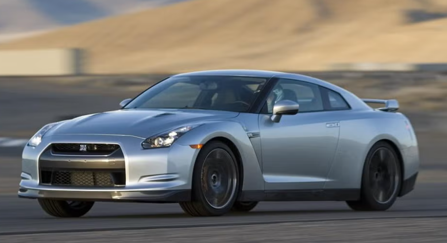
2009 Nissan GT-R (Image courtesy of Car and Driver)
Fast forward to 2014, and a new holy trinity of hypercars has emerged to reshape the automotive hypercar world again: The LaFerrari, the McLaren P1, and the Porsche 918 Spyder. The main technological breakthrough these cars utilized was the use of electric motors alongside their advanced internal combustion engines. They also used the latest and most advanced active and passive aerodynamic components to help control all the power from their powerplants not just in straight lines but also around tight corners and sweeping bends. However, each accomplished this a bit differently from each other. Let’s explore each and see how they’re similar and how they differ from one another.
In the LaFerrari, the powerplant worked by relying on an 6262 cc V-12 that produced 800 chevaux-vapeur (cv), or almost 789 hp, along with an electric motor that produces 163 cv, or almost 161 hp, bringing the grand total output of the system to 963 cv, or almost 950 hp. This system, known as the Hybrid Kinetic Energy Recovery System (HY-KERS), was the first of its kind in a Ferrari. According to Ferrari, because they were able to reduce the weight and the size of the electric motor, they were able to conserve 94% of the electric motor’s power, which is comparable to that of the efficiency seen in an F1 car. The LaFerrari also used a 7-speed dual-clutch transmission, along with modern active and passive aerodynamic elements and suspension tuning.
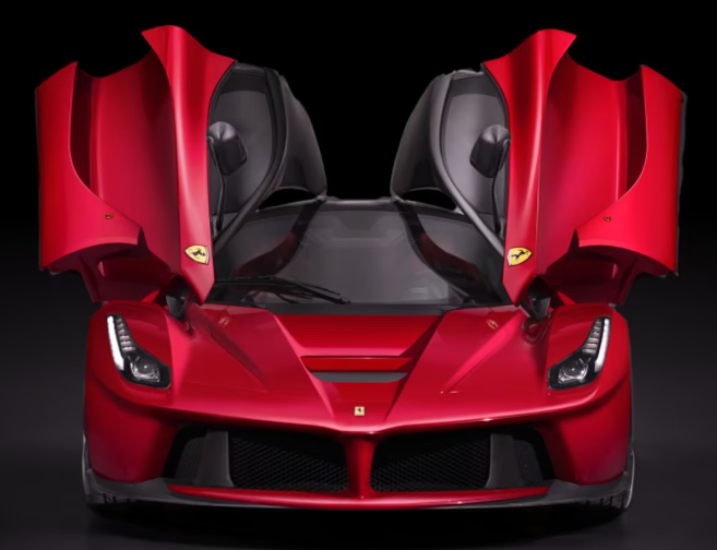
Ferrari LaFerrari (Image courtesy of Ferrari S.p.A.)
In the P1, the idea is the same as the LaFerrari but the execution behind it is a bit different. Instead of a V-12 internal combustion engine (ICE), it’s got a 3.8L twin-turbo V-8 and a single electric motor that produces a combined 903 bhp. Like the LaFerrari, the P1 uses passive and active aerodynamic components to help it navigate tight corners and sweeping turns along the track. According to McLaren, they tested the P1 prototypes in extreme weather conditions, like California’s Death Valley, to make sure all the engine components worked as engineered when driven hard in these conditions.

McLaren P1 (Image courtesy of McLaren Automotive)
Last, but not least, in this automotive holy trinity is the 918 Spyder. Just like the other two, it uses active and passive aerodynamic components and a hybrid powertrain. However, the hybrid system is a naturally aspirated (i.e. no superchargers or turbochargers) 4.6L V-8 with two electric motors rather than one that produces a total output of 887 Pferdestärke (PS), which is almost 875 bhp. Because of the way the car was designed and engineered with this hybrid system, it was the first production car to break the seven minute barrier at the Nürburgring Nordschleife.

Porsche 918 Spyder (Image courtesy of Dr. Ing. h.c. F. Porsche AG)
Almost eleven years later, the automotive hypercar landscape is still evolving, with the latest entry being the 2025 Chevrolet Corvette ZR1 with a 1,064 hp 5.5L twin turbo V-8. It’s already broken multiple lap records at various U.S. racetracks. It’s been designed with track-focused performance and everyday drivability in mind.
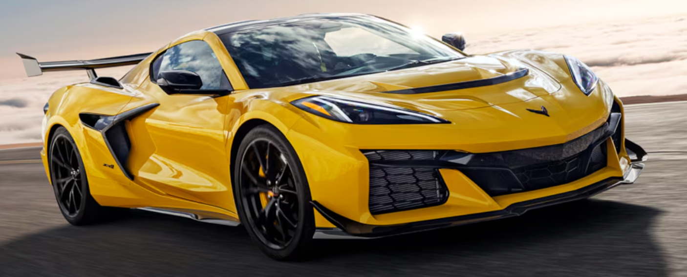
2025 Chevrolet Corvette ZR1 (Image courtesy of General Motors)
So, how do these hypercars manage to handle all this power without overwhelming the driver? How are they engineered to handle everyday road conditions? Let’s take a deeper look into the engineering and cost behind the things that make these cars elite: their chassis, suspensions, wheels, tires, steering, aerodynamics, materials, and energy consumption.
Building From a Solid Foundation
With supercars and hypercars, one of the first areas engineers focus on is the vehicle’s chassis. This is the structural component that plays a crucial role in how the car behaves when braking, accelerating, and cornering. It’s also responsible for providing the necessary structural stiffness that will allow the car to carry various loads such as the driver, the passenger, the powertrain, the body panels, the electronics, and external impacts.
Frank Markus from Motor Trend wonderfully explains in his article “Body-on-Frame vs. Unibody vs. Monocoque: What’s the Difference?” the difference between various chassis types. As we are discussing supercars and hypercars, the two main chassis types that are used are the space frame chassis and the monocoque chassis. Let’s explore to see how both types are engineered and constructed.
In a monocoque chassis, as Frank Markus puts it, “the skin is the shell, bearing tension and compression loads.” This is where the central exterior parts of the car also form its structural chassis. A monocoque chassis helps reduce weight by using the chassis itself to form parts of the car’s body rather than individual body panels, which ensures that the car’s structure is more cohesive, especially since welds in the chassis can potentially create weak points. You can see how companies such as Multimatic use monocoque chassis to help automakers create their vehicles.
Monocoque chassis of a Lamborghini Revuelto (Image courtesy of Automobili Lamborghini S.p.A.)
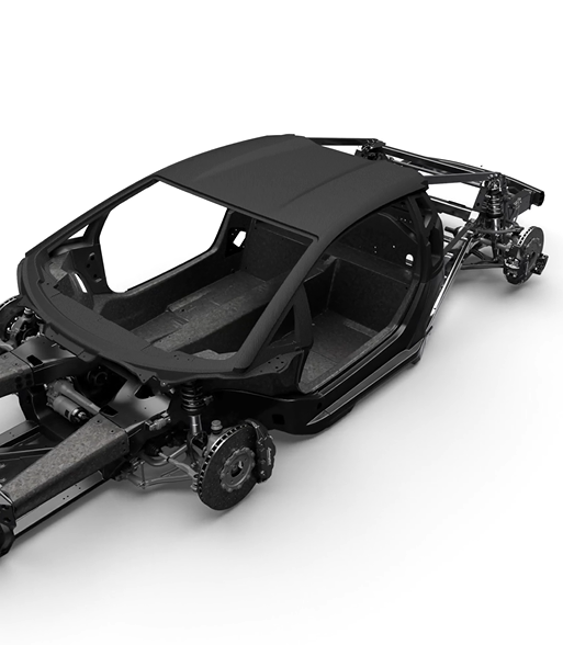
In a space frame chassis, Frank Markus notes that space frame chassis are where “an internal framework of metal tubes or composite stringers bears most of the load while the exterior bodywork bears very little.” Space frame chassis use a series of welds and fasteners to create the internal structural components of the chassis and use body panels to enclose the chassis itself. Even though these types of chassis weigh more than a comparable monocoque, they are easier to construct and can be built more quickly. Just to demonstrate how effective they can be, here’s an article from the Society of Automotive Engineers (SAE) detailing how the C8 Corvette, a car that’s been praised and won numerous awards for its driving dynamics, employs a space frame chassis.
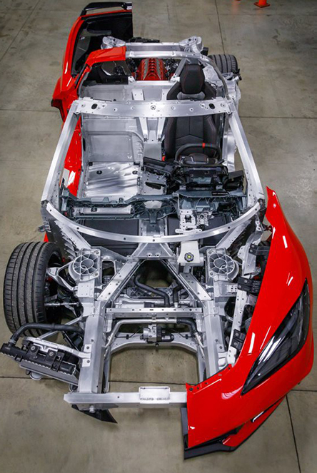
Cutaway of Chevrolet C8 Corvette showing space frame chassis (Image courtesy of SAE International/General Motors)
Regardless of which chassis type an engineering team wishes to choose for their new supercar or hypercar, the chassis needs to allow the car to perform its intended function well. It also needs to ensure it is engineered and designed to handle the loads and forces the car will be subjected to when driving. Most importantly, the engineering team needs to ensure the chassis will provide optimal safety for the occupants inside the car that will minimize injury and maximize survival. Let’s explore the engineering principles automotive engineering teams use when making a chassis that incorporates all of these characteristics well.
Both chassis types will need their structures to account for what are known as indeterminate forces, or the forces that take place within a structure that the principles of statics alone can’t account for. This can be due to the compression and tension in a chassis as Frank Markus points out, or also caused by loads such as occupants and automotive components, or even gravity itself. Let’s look at an example:
Say a metal object is resting at equilibrium. There are internal forces due to gravity that are pulling it down, while there is a normal force from the surface the metal object is resting on that keeps it upright. Even though there is nothing happening externally or the statics behind it, which is just a study of how the metal object physically interacts with the outside world, states that nothing is happening, there are most definitely indeterminate forces at play. These same indeterminate forces are also present in automotive chassis, yet there are far more to account for due to the dynamic nature of the forces and loads the car will experience during its lifetime.
Another aspect that should be considered in chassis design and engineering is the stress and strain the chassis will also be subjected to in various driving conditions. Stress is defined as the amount of force per unit of area, while strain is defined as how much an object stretches or compresses. Here’s an example to help explain these things a bit more clearly:
Let’s use the same metal object in the previous example. If the metal object is pulled at one or both ends, this would cause a positive normal stress since the force would be perpendicular to the surface and directed away from the center of the metal object. As a result, this would cause the object to elongate, or stretch, causing a positive strain on the metal object. If the metal object is pressed at one or both ends, this would cause a negative normal stress since the force would be perpendicular to the surface of the metal object and directed towards its center. As a result, this would cause the metal object to shorten, or compress, causing a negative strain on the metal object. Here’s a formula that helps break down normal stress:
σ = E * ε
σ (sigma): Normal Stress, or
perpendicular force applied
per unit area
ε (epsilon): Strain, or how
much something is
stretched or compressed
i.e.
stretched/compressed
3 in
E: Young’s Modulus, which
is a constant that explains
the relationship between
stress and strain
for a particular material
Measured in either metric Pascals
(Pa) or British Pounds per Square Inch
(psi)
There are also stresses that can run parallel to the surface of the metal object. These
are known as shear stresses. These stresses are responsible for twisting motions within
the object itself. If the metal object were to rotate counterclockwise, then the metal object
would be experiencing positive shear stress. If the metal object were to be rotating in a
clockwise direction, then the metal object would be experiencing negative shear stress.
Here is a formula that helps break down shear stress:
𝜏 = G * 𝛾
𝜏 (tau): Shear Stress, or
parallel force applied per
unit area
𝛾 (gamma): Shearing strain
or angular deformation
Measured in radians
G: Shear Modulus, which is
similar to Young’s Modulus
in that it explains the
relationship between
shear stress and shear
strain for a particular
material
Measured in either metric Pascals (Pa) or British
Pounds per Square Inch (psi)
Both σ = Eε and 𝜏 = G𝛾 are expressions of Hooke’s Law, which describes how the stress exhibited by the metal object are influenced by the material properties (in this case, it would be either the E or G), the stretch or compression of the metal object, and the angular deformation of the object. Engineers must understand and incorporate both these ideas when designing and engineering a supercar and hypercar chassis.
Say that the same metal object is subjected to the elements and is outside quite frequently. Not only would it be exposed to shear and normal stresses, but also to thermal stresses as well. Let’s take a look at some other equations and see how temperature also causes stresses and strains on materials:
ε_T = ⍺ * ΔT
ε_T (epsilon): thermal
strain
⍺ (alpha): coefficient
of thermal expansion
(based upon material
used)
ΔT (delta T): change
temperature
Thus:
𝜎T = -E * εT = -E * (⍺ * ΔT)
𝜎T: Thermal Stress
E: Young’s Modulus
Wait, why is it -E * εT instead of E * εT? It’s because there’s an inverse relationship
between temperature change and the stress and strain it causes on materials. This is one of the reasons why cars like the McLaren P1 were tested in conditions like California’s Death Valley and also in wintry conditions.
In addition to understanding how the indeterminate forces, stresses and strains the car’s chassis is subjected to influence the chassis’ design, engineers must also account for loads, bending moments, area moment of inertia, and center of gravity (C.G.) in the chassis’ overall engineering.
Loads can either be point loads or distributed loads. A point load is when the load is applied and concentrated to one section of either a beam or platform, like a person standing in one location. A distributed load is a load that spans either the entire or a significant portion of a beam or platform, like a parked large semi-trailer truck.
In the case of a supercar or hypercar, a point load would be a person sitting in a seat or a single piece of luggage in a rear or front trunk. A distributed load in this context would be a load that extends for a considerable length of the car, like a body panel, transmission or engine. Ensuring that the chassis’ structural components not only support components that will always be in the car like the engine, transmission, body panels, electrical equipment, or dead loads, but also the passengers, luggage and other cargo the car might need to support, or live loads, is crucial for engineers to understand and consider during the chassis’ design and engineering.
Seeing as how many drivers will attempt to push their supercars or hypercars to the limit, they’ll likely be making sharp turns on either some fun canyon roads or a racetrack. As we previously discussed with indeterminate forces, this will cause the car’s chassis to bend based on the forces and loads exerted onto the chassis. When you take this force and see how it’s applied to a location that is a certain distance away from either a connecting point or a weld, you would be calculating the bending moment, or simply called the moment, at that particular location. Let’s look at the formula to better understand what moments are:
M = F * r
M: Moment or Bending Moment
F: Applied Load or Force
r: distance from either the starting point or connecting point of the
structural member
Measured in lb·ft or N·m
I discuss how this is similar to torque in “Carrying Up a Heavy Load”, which you can find here. In terms of chassis design, however, the bending moment must not produce any movement, which is another reason why selecting appropriate materials and engineering a viable design is of utmost importance.
So, how do automotive manufacturers ensure that the components of the chassis don’t bend or twist? Well, they use two different methods: Area Moment of Inertia and Polar Moment of Inertia.
Engineers use Area Moment of Inertia to ensure the structural member doesn’t bend, or experience deflection, and Polar Moment of Inertia to ensure these structural members don't twist, or experience torsion. Let’s take a look at both methods and see how they are used in conjunction with bending moments.
In area moment of inertia, automotive engineers ensure that the structural members in a chassis don’t bend. They do this by analyzing the shape of the structural members’ cross-sections, or the shape of the structural member if it was cut perpendicular, or 90°, to its length. Here’s the formula for area moment of inertia:
I_x = ∫ y^2 * dA
I_x: Area Moment of Inertia with
respect to the x-axis
y: measurement along the y-axis
dA: per infinitesimal (small) unit of
area
I_y = ∫ x^2 * dA
I_y: Area Moment of Inertia with
respect to the y-axis
x: measurement along the x-axis
dA: per infinitesimal (small) unit of
area
-Both measured in m^4 or ft^4
So, why are we calculating the area moment of inertia with respect to one axis by measuring the cross section’s distance using the other axis? Let’s think about how a long pool noodle bends. Even though the pool noodle is being bent along the x-axis, the bend itself is orienting towards the y-axis. This phenomenon, like the one seen in the pool noodle example, is why we measure the distance along one axis to see how the structural member will bend with respect to the other axis.
Notice how the material type was never mentioned in this discussion. This is because the area moment of inertia is the same for the same cross-sectional area, regardless of the material the structural member is made out of. Some shapes, like rectangles, squares or circles, have their own distinct formulas to measure their area moment of inertia, but you could still use these general formulas to accurately calculate their area moment of inertia as well.
Just a quick little note: if an engineering team wants to calculate the area of inertia in a beam that doesn’t pass through its centroid, or an object’s geometric center, they will most likely use the Parallel Axis Theorem:
I_parallel = I_centroid + d^2 * A, where:
I_parallel is the area moment of inertia about the new axis,
I_centroid is the area moment of inertia about the centroid axis,
d is the distance between the centroid axis to the parallel axis, and
A is the cross-sectional area.
It’s great that we now understand how automotive engineers are able to determine if a shape can resist bending, but what about torsion, or twisting? How can engineers determine if a structural component will not twist so easily? Thankfully, engineers have another tool they can use: Polar Moment of Inertia.
With polar moment of inertia, engineers can take a look at how circular structural members, like cylinders or tubes, respond to torsion. Let’s take a look at the formula and see how engineers use this to their advantage:
J = (𝜋/32) * d^4
J: Polar moment of
inertia
d: diameter of
cylinder
Used in solid cylinders only
J = (𝜋/32) * (d_o^4 - d_i^4)
J: Polar moment of inertia
d_o: outer diameter of
cylinder
d_i: inner diameter of
cylinder
Used for hollow cylinders (tubes) only
-Both measured in m^4 or ft^4
Just like in area moment of inertia, the polar moment of inertia is entirely dependent on the geometry of the tube. Thanks to both area moment of inertia and polar moment of inertia, engineers can more effectively design chassis that are safe and reliable.
Even with all this complexity in chassis design and engineering, automotive engineers still need to determine the car’s center of gravity (C.G.), or the central point of the car’s mass with respect to its length, width and height. To prevent the car from excessive roll, or the side-to-side rocking motion in a supercar or hypercar, the engineers will try to ensure the car’s C.G. is as low as possible. Here is how engineers determine a car’s C.G.:
x = Σ(W * x_i) / ΣW
x: C.G. along the x-axis
W: weight of individual
element
x_i: x-coordinate for C.G.
of individual element
y = Σ(W * y_i) / ΣW
y: C.G. along the y-axis
W: weight of individual
element
y_i: y-coordinate for C.G.
of individual element
z = Σ(W * z_i) / ΣW
z: C.G. along the z-axis
W: weight of individual
element
z_i: z-coordinate for C.G.
of individual element
Altogether, these equations determine the supercar’s or hypercar’s C.G. If engineered correctly, the car’s center will be concentrated near its geometric center and be positioned low to the ground. This is crucial for having a car like the upcoming McLaren W1, Ferrari F80 and Chevrolet Corvette ZR1X to handle a racetrack’s corners with ease.
These supercars and hypercars will also most likely be driven on public roads, even if for relatively short distances. Because of this, their chassis need to be able to comfortably transport people as well. This is where studies involving noise, vibration and harshness (NVH) come into play. Let’s see how both the monocoque chassis and space frame chassis are able to handle NVH from the roads they drive on.
Since we’ve already studied how the parts of a structural monocoque chassis become the exterior part of a car’s body work, it is easy to see why these cars are prone to higher NVH levels. Conversely, cars built using a space frame chassis structure will experience lower NVH levels since the exterior body panels in these cars will absorb more from the road. This is why cars such as the Audi R8 and the upcoming Lamborghini Temerario are created with a space frame chassis and why cars such as the Porsche 918 Spyder, McLaren W1 and the Lamborghini Revuelto need added electronics and components to make their rides better suited to the road.
Since these cars will likely be driven on the road, they will also be more likely to get involved in accidents. Automotive engineers will need to design these chassis to be able to absorb impacts and protect the driver and occupants from harm or danger. Thankfully, engineers of both monocoque and space frame chassis cars have designed designated crumple zones that absorb the energy from the impact. Furthermore, engineers have also designed sections of the car, like its A and B pillars, that are stiff and rigid to deflect energy away from the car’s occupants.
Even though the occupants might be safe during and after a crash—which is the most important thing—the effects of a crash on a monocoque chassis and a space frame are quite different. Since a monocoque chassis tends to be one cohesive unit, repair times and costs might be much more substantial or economically unfeasible. A space frame that might have similar damage, on the other hand, might have a much higher chance of being replaced since it's made up of multiple components rather than just one big unit.
So, how are engineers able to incorporate all of these considerations and engineering practices into a single chassis? Do they still do everything by hand as they did in the early days of creating sports cars and supercars? Thankfully, they don’t need to rely on traditional paper and pencil methods to create the ultimate supercar and now use sophisticated computer programs and the latest engineering know-how to make these chassis. Let’s explore the cutting edge software these brilliant engineers use to make these chassis stand up to everything a race track or Mother Nature throws its way.
Automotive engineers use cutting edge computer-aided design (CAD) software, like CATIA or SolidWorks, to create the space frame chassis, monocoque chassis, body panels, or any other part the car will need. This is done by setting the program to a scale and using the built-in features in CATIA or SolidWorks to create the desired part or assembly. However, as great as these CAD software systems are, they still aren’t able to tell the whole story of chassis engineering like the next set of software systems are.
The next set of software systems are known as Finite Element Analysis (FEA) systems that help engineers see loads and stress points on a chassis or other critical automotive part. Companies like Ansys provide wonderful resources to engineers that allow them to make critical decisions in less time and more effectively. These systems use a matrix system consisting of numerous elements to help engineers pinpoint stress areas or places that will need to carry the greatest loads. Let’s unpack this terminology further to better understand FEA systems.
In an FEA system, an automotive part will be shown as a matrix. This matrix is a collection of attached elements. These elements are created from nodes that are used to create the element boundary. The nodes in these elements can have varying degrees of freedom, or varying ways they can move about the plain. There are two main element types that are used in engineering: H-elements and P-elements.
H-elements are the most commonly used elements in mechanical engineering. They are limited, however, to behaviors that can be expressed by a quadratic mathematical equation. Due to this limitation, areas in the matrix that might experience higher stresses and loads have greater quantities of smaller-sized H-elements to accurately depict the stresses and loads in that particular area.
The other element type, the P-elements, are a bit more nuanced than H-elements are. They can interpolate stress and load behaviors that can only be explained beyond that of a quadratic formula. Since P-elements are able to interpolate in this manner, meshes that use P-elements will have fewer and larger elements compared to a comparable mesh using H-elements. It is important to note that, since the P-elements are interpolating over larger areas, the FEA results may not be as accurate as a mesh containing P-elements.
Granted, even with all of this technology available for use, automotive engineers must also still use the knowledge they learned in industry and school. CAD and FEA are powerful tools engineers can use, not replacements for the theory and understanding that can only be provided through a quality engineering education. However, thanks to recent FEA and CAD developments, automotive engineers are able to make decisions to create world-class chassis for hypercars and supercars faster and better than ever before.
Handling Life’s Twists, Bumps and Turns
It’s amazing to see all the engineering that takes place to ensure the chassis can safely and effectively help the car carry out its intended function. However, there is more to a car than its chassis, like the springs, dampers, shocks, suspension, wheels, and tires that help translate the power down to the road. How do automotive engineers design and create suspensions for supercars and hypercars that can both attack the track and take a cruise throughout the city?
The answer lies in the suspension set up and the wheel design for the car. In terms of the supercars and hypercars we are exploring in this article, the most common types of suspensions are short-long arm (SLA)—otherwise known as a double wishbone—suspensions and multi-link rear suspensions. Other high performance vehicles have utilized pushrod suspensions, but for the context of this article, we will only discuss SLA and multi-link rear suspensions. Let’s see how these two suspension types work.

Typical setup of a front SLA suspension (Image courtesy of Altair Engineering, Inc.)
In an SLA suspension, the upper and lower control arms that are used to stabilize the wheel are of unequal length, with the upper control arm usually being shorter than the lower control arm. Some variations of SLA suspensions have either a simple lateral link to replace the upper control arm or a lateral link and an angled tension strut for the lower control arm. The SLA suspension can be adjusted for things like the sideways angle adjustment and the front/back wheel angle adjustment (a wheel’s camber and toe, respectively) and also track width geometry of the suspension to prevent excessive tire wear.
Let’s take a closer look and see why SLA suspensions are designed the way that they are. The long lower control arm is used to help provide a good lever and spring ratio for the suspension. The short upper control arm is used to help adjust the wheel’s sideways tilt, or camber. It’s worth noting that careful refinement of the geometry of these components is necessary to ensure good performance—both on and off the track.
SLA suspensions typically work best in cars that are built with subframes that support the engine as places to mount the suspension and absorb loads. With reference to the engine subframe, they are also very suitable for front engined cars. This is because an SLA suspension geometry allows room for a large engine.
In the case of supercars and hypercars, these suspensions are used as front suspensions in cars like The Ferrari SF90 Stradale, the 2014 Cadillac CTS-V, and the 2009 Nissan GT-R. Some automakers have gone further and have been able to effectively use them as both front and rear suspensions, which can be seen on display in cars such as the Audi R8, 2025 Corvette ZR1/2026 Corvette ZR1X, McLaren F1, Porsche Carrera GT, the 2005 Ford GT, and the 2017 Ford GT (the 2017 Ford GT does, however, use pushrods to activate the torsion bar and coil springs to improve packaging and reduce weight).
However, other high performance cars use a multi-link rear suspension, such as the Ferrari SF90 Stradale, the 2014 Cadillac CTS-V, and the 2009 Nissan GT-R. This suspension setup utilizes linkages that are connected to each other via ball joints. They can either be a three-link, four-link, or five-link setup. Let’s see how each of these setups works:

Typical setup of a rear multi-link suspension (Image courtesy of Altair Engineering, Inc.)
A three-link suspension is suited to handle up/down, front/back, and left/right turning motions; a four-link suspension is suited to handle up/down and front/back motions; a five-link suspension is suited to handle only up/down motions. Furthermore, these suspension setups require less room and weigh less than a comparable SLA suspension setup would since SLA suspensions require larger triangular upper and lower control arms, making multi-link suspensions the preferred suspension setup for high performance cars.
For most supercars and hypercars, since multi-link suspensions are rear suspensions and because the role of the rear is to help stabilize the car, supercars and hypercars with a multi-link suspension have suspensions consisting of five links. Like SLA suspensions, multi-link suspensions attach to either the chassis or subframe of the car. This helps the wheel move independently and more likely to respond to bumps in the road.
So, why do some supercars and hypercars have SLA suspensions for both the front and rear while others have an SLA suspension in front and a multi-link suspension in the rear? The answer lies in two key areas: complexity and use. It’s generally assumed that certain high performance cars won’t be driven as much due to their price or prestige. Since two of the main goals of automotive production are to reduce the amount of resources and utilize each amount of space as much as possible, the multi-link rear suspension is usually the preferred choice for these cars.
However, multi-link suspensions are connected through a series of links and ball joints, which are more complex and take longer to produce than the triangular upper and lower control arms found on SLA suspensions. Also, since links in a multi-link suspension are connected to each other via ball joints and can have more than two degrees of freedom (DOF), where one DOF equals bidirectional movement vertically (up/down), longitudinally (front/back), horizontally (left/right), or rotationally turning left or right, this can lead to greater wear and tear on the suspension. SLA suspensions, on the other hand, have at most two DOF and are prone to less wear and tear than a comparable multi-link suspension. If the supercar or hypercar is designed to be both a daily driver and a race track weapon, then an SLA setup would be the best rear suspension choice.
So, now that we have a solid understanding of the two main suspension systems in high performance cars, how do engineers ensure SLA and multi-link suspensions are as effective as possible? How can they ensure the upper and lower control arms keep the wheels stabilized during daily or spirited driving? How can engineers ensure the suspension helps minimize or reduce road imperfections from being transmitted into the cabin? The answer to these questions lies in two components: the suspension’s springs and dampers.
The springs and dampers usually come as one unit. They are attached to the lower control arm or one of the lower links in an SLA or multi-link suspension, respectively. The way springs and dampers are made helps keep the unit compact to take up as little space as possible and maximize the effectiveness and efficiency of the spring/damper assembly. Let’s analyze both the spring and the damper individually and see how each contributes to the car’s stability.
The springs in the assembly push down on the lower control arm or one of the lower links to ensure the wheel stays in place. The force that the spring pushes down on the lower control arm or one of the lower links can be explained by physics. Let’s look at an equation that models the force a spring exerts when it pushes against the suspension:
F_s = k * Δl
F_s: Force of the
spring
k: spring constant
(stiffness)
Δl: change in
spring’s length
(compression or
extension)
So, by measuring how stiff the spring is and by evaluating how much the spring’s length changes, we can see how much force the spring exerts on the lower part of a suspension.
So, how do dampers help the springs in chassis dynamics? Well, the damper’s role is to minimize and eventually stop the oscillating motions of the spring. Here’s an explanation of damping and here’s the formula to calculate damping force:
F_D = -b * v
F_D: Damping Force
b: Damping Constant
v: Velocity of hydraulic fluid inside the
damper
So, why is the damping force negative? Because, as we discussed earlier, dampers minimize and eventually stop the oscillating motions of the spring, meaning that the damping force counters the spring force; thus the damping force in the context of springs is negative.
So, how do we know if the damping force is just right? Let’s take a look at the damping constant, b, and see how this can help us determine if the damping force from the damper is not enough, just right, or too much. To help us make this determination, let’s use the formula b = sqrt (4 * m * k), where b is the damping constant, m is the mass of the sprung mass, or the portion of the car supported by the car’s springs that include the chassis and everything that uses the chassis as a foundation (i.e. powertrain, cabin, lights, electronic systems, cargo), and k is the spring constant:
If:
•b < sqrt (4 * m * k),
then the car is
underdamped and the
dampers are not as
effective as they should
be. The car’s pitch (the
up/down movement of
the front and back of the
car) will take longer to
stabilize
•b = sqrt (4 * m * k),
then the car is critically
damped and the
dampers are effectively
controlling the car’s
pitch
•b > sqrt (4 * m * k),
then the car is
overdamped and the
dampers are too
aggressive. This means
that the car’s springs
will return to their
normal state, or
equilibrium, longer and
may make the
suspension feel
sluggish as a result
For supercar and hypercar makers, the dampers need to be made in such a way that the car will be critically damped, no matter what kind of road surface the car is driving on.
Well, we’ve gone through the springs, dampers and upper/lower control arms of a suspension, so that should give a car enough technical hardware to handle the sharpest corners, right? Well, that’s mostly true, but there are two more components in a supercar’s or hypercar’s suspension that are needed to ensure the wheels never come off the ground, which would be the car’s front and rear anti-roll bars. Let’s take a deeper look and see how anti-roll bars work.
Anti-roll bars connect the two independent front or rear suspension components together. If one wheel is pushed up when driving or cornering, the anti-roll bar turns and produces a torque (T), which is equal to the force exerted by the independent suspension onto the anti-roll bar (F) times the turning radius (r), and transmits this torque to the other wheel via the linkage it has with the independent suspension, causing the other wheel to be pushed up as well. Here’s the torque formula to help better understand this phenomenon:
T = F * r
T: Torque
F: Force
r: Radial distance
between applied
force and turning
center
-measured in lb·ft or N·m
Very similar to the bending moment discussed in the chassis section of this article, torque is calculated the same way, but torques are meant to move the bar while bending moments are used to determine how to make structural components in a chassis not move. However, to ensure the anti-roll bars don't fail, automotive engineers must make sure that the torsional resistance—read the polar moment of inertia explanation in the Building From a Solid Foundation section if you need a refresher—of the front and rear anit-roll bars are sufficient to withstand their twisting motions, which could limit the effectiveness of the anti-roll bars. Nonetheless, thanks to torque, the hypercar’s or supercar’s front and rear anti-roll bars are able to help keep its wheels on the ground during hard cornering.
As seen in Engineering Explained’s video, the components of the anti-roll bar are held together and kept in place by bushings. Furthermore, other sections of the suspension are held together via bushings. How do bushings work, exactly? Let’s find out together.
Bushings are hollow cylindrical components that are designed to reduce wear and friction. They do this by supporting rotational components in the car’s suspension and are able to hold it in place as the bushings themselves are mounted to the structural components of the car. Because of bushings, anti-roll bars and suspension components can rotate without becoming misaligned. Here’s more information from Società Italiana Boccole that explains bushings and the materials they’re made out of in more detail.
To make sure the bushings are operational and structurally sound, many use durometers to measure the hardness and durability of the car’s bushings. Quality bushings help ensure the car’s noise, vibration and harshness (NVH) are within acceptable limits and keep the car’s suspension parts where they need to be. Here’s more information from Suspension.com that describes in more detail the various methods used to ensure a car’s bushings are top-notch.
Great, so now we understand chassis and suspension dynamics, but what good is it all if the car doesn’t have wheels and tires to help it move? Do engineers even care about wheels as much? The answer: yes, they definitely care about wheels, from the materials they’re made out of to the shape and materials they use to make the wheel. Let’s take a closer look at the engineering that goes into a supercar’s or hypercar’s wheel.
Wheels are important because they transmit the power generated by the car’s engine to the tires. They also help carry the momentum and speed of the car on long roads or through tight corners. Since they also house the car’s brakes, wheels must also serve as a means for the brakes to dissipate heat. If the wheels on a supercar or hypercar are not able to carry out these essential functions well, then the car’s performance as a whole can be compromised. To reiterate: yes, wheels are very important and automotive engineers know it.
To account for the wide contact patch the tire will need for grip and traction with the road, the wheels will need to be just as wide for the tire to be correctly installed onto the wheel. Since the wheels house the car’s brakes, the wheels will need to be a large enough diameter to ensure the brakes are covered while also making sure there will be as little turbulent air inside the wheel housing as possible. Furthermore, on top of taking into account the turbulent airflow in the wheel housing, the wheels must be able to support or enhance the supercar’s or hypercar’s overall aerodynamic profile.
As previously mentioned, the wheels will need to be light enough to help fulfill the supercar’s or hypercar’s purpose of providing the highest level of performance possible. To ensure this, engineers will need to utilize the moment of inertia about the wheels to see how much energy each wheel will need. Let’s take a look into the moment of inertia equation and see what it means for wheels on high performance vehicles:
I = m * r^2
I: moment of inertia
m: mass of wheel
r: radius (half the
diameter) of the
wheel
-measured in kg/m^2 or slug/ft^2
Since wheels are essentially hollow cylinders, this is the moment of inertia equation that’s most often used for wheels. Other equations for moment of inertia can be found in the link contained in the previous paragraph. Regardless of which moment of inertia equation is used based on the shape the engineer is working with, the objective is still the same: ensuring the moment of inertia is as small as possible by using the lightest and most durable materials for the wheel.
So, now that we’ve discussed the importance of wheel design, it is important to discuss how these wheels can be altered to better serve the intended purpose of supercars and hypercars. Original Equipment Manufacturer (OEM) companies can adjust the wheel’s toe and camber. Let’s look into both a wheel’s toe and camber and see how they can affect the handling and performance for supercars and hypercars.
In automotive engineering, a wheel’s toe is simply the way the front and rear portions of the wheels are angled. A car is said to have toe-in geometry if the front of the wheels are pointing into the wheel housing. This type of geometry helps the car maintain straight-line stability. If someone were to see this in a car on the road, it would most likely be seen on the front wheels of a rear-wheel drive (RWD) car since power is transmitted through the car’s rear wheels and could lead to rear-end instability.
On the other hand, a car is said to have toe-out geometry if the front of the wheels are pointing away from the wheel housing. This type of geometry assists in vehicular agility around corners and tight turns. This type of geometry is most likely seen on the front wheels of a front-wheel drive (FWD) car since power is transmitted through the car’s front wheels and may need extra support to help the car turn at higher speeds.
Toe is used not only by OEM companies but also by those who modify OEM cars to help improve handling characteristics. You can see more about toe from Engineering Explained’s wonderful video explaining toe geometry.
Another wheel geometry used by engineers is camber. This is measured by the angle the wheel makes with the vertical axis. A car is said to have positive camber if the wheel creates a positive angle with the vertical axis; that is, if the top of the wheel points away from the car. This wheel geometry can be seen in vehicles driving on uneven terrain, such as heavy-duty trucks or off-road vehicles.
Negative camber, on the other hand, refers to a wheel that creates a negative angle with the vertical axis. This is another way of saying that the bottom of the wheel points away from the car, which is opposite of what happens when wheels have positive camber. This type of wheel geometry can be seen in vehicles like Japanese Domestic Market (JDM) tuner cars or other similar high-performance vehicles.
Now is where the rubber hits the road, literally. Tires are the reason why hypercars and supercars are able to be driven safely on the road and effectively use the power produced by their engines to attack a racetrack or canyon road. Let’s examine how tires are constructed and see how their construction allows supercars and hypercars to reach maximum performance.
In supercars and hypercars, the name of the game when it comes to handling is to attack the corners as effectively as possible. This means going through corners quickly and steadily with the least amount of effort. In order to accomplish this, the tires need to be able to stick to the road as best as they can, which is done by making the tires as wide as possible while also using as little tread on the tires themselves. This increased surface area improves traction by increasing static friction between the tire and the road and decreasing kinetic friction. Let’s take a dive into static and kinetic friction and see why static friction is the preferred kind of friction in this scenario.
Static friction refers to the friction force that keeps an object on a surface and doesn’t allow the object to slip or move. Let’s take a look at the equation:
F_s ≤ 𝜇_s * N
F_s: Force of
Static Friction
𝜇_s: Coefficient of
Static Friction
N: Normal Force
(force from ground
pushing on the tire)
Notice how the equation is F_s ≤ 𝜇_s * N rather than Fs = 𝜇_s * N. Why is that? Well, if the Force of Static Friction is greater than that of 𝜇_s * N, that means the tires will no longer stick to the road and, thus, start skidding, or sliding, on the road.
Well, what’s the force called when the tires start skidding on the road? That’s the result of kinetic friction at work. Let’s see how kinetic friction works and how both static and kinetic friction compare to one another.
F_k = 𝜇_k * N
F_k: Force of
Kinetic Friction
𝜇_k: Coefficient of
Kinetic Friction
N: Normal Force
(force from ground
pushing on the tire)
Notice how the equation is F_k = 𝜇_k * N rather than F_k ≤ 𝜇_k * N or F_k ≥ 𝜇_k * N? That’s because when the tires are sliding along the ground, 𝜇k will always remain constant as long as the car is driving along the same concrete or asphalt surface and the ground will always transmit the same normal force to the tires, meaning that Fk will be constant. Furthermore, let’s see how Fs and Fk compare.
F_s, max > F_k
Wait, why is that? Have you ever noticed when you push a heavy object—like a refrigerator—that it’s harder to get it moving than it is to actually move the object once it’s moving? Other than inertia, or an object’s resistance to move, the static friction the object has with the floor also prevents the object from moving. This is because:
𝜇_s > 𝜇_k
Engineers use this fact to make sure that not only the tires have the greatest amount of contact patch, or the surface area of the tire directly in contact with the road surface, but also to ensure that the tires are made from rubber that will produce the greatest amount of static friction with the road and minimize the chance of kinetic friction.
Because of this, many OEMs work with tire manufacturers like Goodyear, Michelin, Pirelli, and Bridgestone. Not only will these strategic partnerships help OEMs ensure that their supercars and hypercars stay glued to the road, but that the tires will help support the weight and loads of their cars on a racetrack or around town. Let’s take a closer look at how tire manufacturers create tires that allow the tires’ side walls and cornering stiffnesses enhance the supercar’s or hypercar’s performance.
The tire walls provide support to the sprung—refer to the damping forces explanation in this section for a refresher on spring mass—and unsprung mass of the car, which is the portion of the car not supported by the springs and dampers of the supercar or hypercar (i.e. wheels, tires, control arms, anti-roll bar, tie rods, etc.). The tire walls also need to handle the loads exerted on it by cornering and daily driving. Because of this, tires have unique ratings based on OEM and tire manufacturer standards. These standards should be adhered to for optimal performance and safety to the driver and the general public.
In supercars and hypercars, the main area of concentration is a tire’s cornering stiffness, or the lateral force a tire can withstand when the tire is at a zero-slip angle, or when the angle of the tire is perfectly upright. Here is a video from Engineering Explained that explains slip angles very well. Cornering stiffness of both tires is denoted as C𝛼 and is defined as opposite of the change in the horizontal force (F_y) with respect to the slip angle (𝛼). Here’s the formula:

The listed formula is a mathematical expression of what was explained in the previous paragraph. If you understand that explanation, then you have an understanding of the formula.
So, how does C𝛼 apply more directly to tires? Well, let’s take a look at some more formulas below:
Cornering Force of two tires (F_y) = C⍺ * slip angle (⍺)
Cornering Force of one tire (F’_y) = C’⍺ * slip angle (⍺)
C’⍺ = a * Fz - b * Fz^2
a: First coefficient in cornering stiffness
polynomial
b: Second coefficient in cornering stiffness
polynomial
Fz: Load on one tire
C⍺ = (a * F_zo - b * (F_zo)^2) + (a * F_zi - b * (F_zi)^2)
F_zo: Force on Tire 1
F_zi: Force on Tire 2
So, not only do we have relationships between forces on each and their corresponding cornering stiffnesses, but we are also able to see how each tire on the axle contributes to the overall cornering stiffness of both tires on the axle. Because of these calculations and observations engineers go through during tire development for their supercars and hypercars, it is of utmost importance to use the correct tire for its intended purpose.
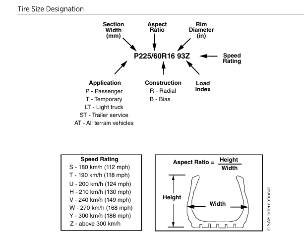
Tire Size Designation based on vehicle type and intended function (Gillespie 278)
Steering Everyone in the Right Direction
Well, now that we understand the engineering behind a supercar’s and hypercar’s chassis, suspension, wheels, and tires, we need to understand how the car is able to make those sharp turns. Thankfully, steering has been an integral part of driving since the early days of the automobile like the one Robert Allison bought on April 1, 1898, but it has radically changed since then. So, how do steering systems operate in modern hypercars? Let’s explore the modern-day steering systems in supercars and hypercars together.
The steering system in supercars and hypercars is still mainly rack-and-pinion setup, while others are beginning to implement a steer-by-wire system. The rack-and-pinion system is a steering system where either the driver’s or autonomous system’s input—like General Motors’ Super Cruise or Ford Motor Company’s BlueCruise—connects directly to the steering column which directly connects to the rack-and-pinion setup on the front axle. Power steering also assists the driver’s or autonomous systems input and can be either electric power steering (EPS) or hydraulic power steering (HPS). This J.D. Power article describes how even though EPS is a relatively new technology, it’s the preferred power steering system due to fewer parts, less maintenance because they don’t require fluid changes, and weigh less. This makes EPS a wonderful choice for the new and latest supercars and hypercars.
Some hypercars, like the Porsche 918 Spyder, have rear-wheel steering to help increase driving engagement and performance. Other cars, such as the new Ferrari F80, use electronic systems like Ferrari’s Side Slip Control. Others like the upcoming McLaren W1 will use torque vectoring to help the car maneuver in any environment. No matter the technology, one thing is for certain: supercar and hypercar OEMs will always be searching for ways to improve steering technology and effectiveness.
How does the steering connect to the wheels? It does so via hardware known as a steering knuckle. In cars with independent front and rear suspensions, the steering knuckle connects each wheel to the suspension’s upper and lower control arms, the wheel hub or spindle, the brake rotors, and — in the front — to the steering system’s tie-rods. Some cars with rear-wheel steering, like the Porsche 918 Spyder, have very similar steering knuckle setups for both the front and rear wheels.
In supercars and hypercars, the way the car steers is a result of all the suspension, chassis, wheels, tires, and steering system are all set up. When designed to the highest standard, the car will most likely steer with exceptional precision. If any one of these parts or systems is not tuned exactly as it should, then the car’s steering will be affected negatively. Let’s explore the different types of steering and how they might affect high-speed driving performance.
The best kind of steer a car can have when driving is called neutral steer. Described as being “linear” in feel, this is when the car steers directly to where the driver wants to go. This can happen when the relay linkage connecting the tie-rods to the wheel is aligned to the ideal center of the steering arm ball travel. Unfortunately, there are cars that do not have this kind of steer and exhibit either oversteer or understeer instead.
The car is said to have oversteer if the car turns into a corner more sharply than what was demanded of it by the steering input. This can happen when the relay linkage connecting the tie-rods to the wheel is placed higher than the ideal center of the steering arm ball travel. If the car doesn’t turn into a corner as sharply as the driver demanded of it by the steering input, then the car is said to have understeer. Understeer happens when the relay linkage connecting the tie-rods to the wheel is placed lower than the ideal center of the steering arm ball travel.
Cars that are not driven at high speeds may utilize Ackermann geometry to help them maneuver around town more effectively. The Ackermann geometry setup is where the wheel inside the turn rotates at a greater angle than the outside wheel does. This design was inspired by the idea that the inner wheel has to track a smaller inner radius. It’s important to note that steering systems incorporating an Ackermann geometry may vary in design and engineering complexity based on the vehicle’s design or packaging constraints. Here are the formulas that explain the behaviors of the inside and outside wheels during low speed turns that utilize Ackermann geometry:
𝛿_o =
tan^-1 ( L / (R + ( t/2 )) ) ≊ ( L / (R + ( t/2 )) )
-outer front wheel turning
angle calculation
𝛿_i =
tan^-1 ( L / (R - ( t/2 )) ) ≊ ( L / (R - ( t/2 )) )
-inner front wheel turning
angle calculation
L: Wheelbase of vehicle
-Distance between front
and rear wheels
R: Turning radius
-radius of circular path
during a vehicle’s turn
t: Track width
-distance between
centers of both wheels
-calculated in radians
If this is used in low speed turns, then what’s the point of discussing Ackermann geometry in an article going through the engineering dynamics of supercar and hypercar handling? Well, as it turns out, some supercars and hypercars incorporate partial Ackermann geometry into their steering systems in order to produce the desired turning outcome. Others might use anti-Ackerman geometry, where the outside wheel rotates at a greater degree during a turn than the inside wheel does. Others use parallel geometry where both wheels rotate at the same angle during a turn. Depending on the goals of the car’s steering system, engineers may select anti-Ackermann geometry, a blend of Ackermann and anti-Ackermann, or a parallel steering setup.
Stop for Goodness Sake!
It’s great that a car can turn and adapt to road conditions, but what if the driver needs to slow down? How can the driver safely bring the car to a halt? That is where the car’s brakes come into play. Let’s see how braking systems work in supercars and hypercars.
In production cars there are two main types of brakes: drum brakes and disk brakes. Drum brakes work using a set of springs connected to leading and trailing shoes that press against the drum, which is attached to the wheel hub. Due to kinetic friction, the drum brakes eventually slow the car to a halt and remain stationary due to static friction. Because of their relatively simple design they were used in smaller economy cars.
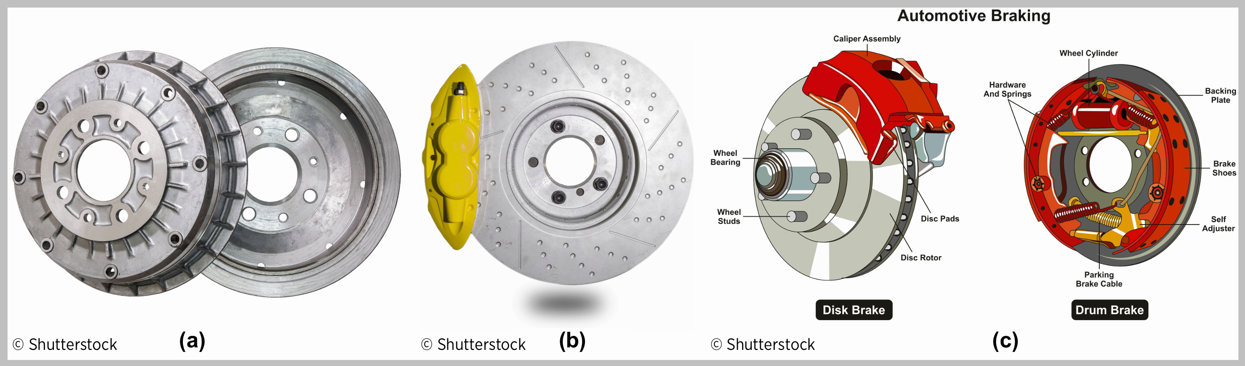
Figure 3.1: Drum Brake and Disc Brake (Gillespie 45)
However, since supercars and hypercars use disc brakes, this article will mainly focus on analyzing the parts in those braking systems. The reason why supercars and hypercars utilize disc brakes over drum brakes is because drum brakes are more likely to exhibit greater torque variation during braking than disc brakes due to temperature fade and the velocity effect, which is a phenomenon where torque increases as the car’s velocity decreases. This can make it harder for the car to maintain balance between the front braking effort and the rear braking effort during maximum-braking stopping. This can be problematic when a supercar or hypercar goes around a tight corner and will need to slow down.
Disc brakes are comprised of four main components:
Rotor: attached to the wheel hub, this is the “disc” part of the brake and can be made out of either steel or carbon-ceramic. Due to the high temperatures and extreme loads that take place under hard braking in a supercar or hypercar, carbon-ceramic brakes are the preferred standard. Carbon-ceramic brakes can handle higher heat and resist fade better than their steel rotor counterparts. The first production vehicle to have carbon ceramic brakes was the 2000 Mercedes-Benz CL 55 AMG F1 Limited Edition.
Caliper Assembly: this is the part of the braking system that houses both the brake pads and the pistons that press the brake pads to the brake rotor. For example, the famous brake maker Brembo is known by the insignia they put on their brake calipers.
Brake Pads: these are the parts of the braking system that make contact with the brake rotors and create the kinetic friction similar to what is seen with the leading and trailing shoes in drum brake systems. The pads can either be made from a ceramic or semi-metallic material.
Pistons: these components of the braking system are what allow the brake pads to make contact with the brake rotor. This can be powered via the driver’s or automated system’s input via hydraulic fluid or by an electrical system.
When designing disc brakes for a supercar or hypercar, it is important to keep in mind the brake force that will be generated and the corresponding brake torque as a result of that force. Here are how automotive engineers define brake torque and brake force:
T_b = f (P_a, velocity, temperature)
T_b: Braking Torque
P_a: Actuation effort, or the
effort caused by pressing on
the brake pedal
f: a mathematical way of
explaining that brake torque
is a function of actuation
effort, velocity and
temperature
F_b = ( T_b - (I_w * 𝛼_w) ) / r
F_b: Braking Force
T_b: Braking Torque
I_w: Moment of inertia of
wheels and drive
components (if you need a
refresher on moment of
inertia, review the moment of
inertia explanation towards
the end of the Handling
Life’s Twists, Bumps and
Turns section, where the
article goes into detail about
behind a wheel)
𝛼_w: Rotational (or angular)
deceleration of wheels
r: radius of wheels
If the brakes aren’t locked, or if the brake rotors and wheels are still moving while the car is still moving, then engineers can calculate deceleration a_x by taking 𝛼_w and dividing it by r. More clearly:
a_x = 𝛼_w / r
Also worth mentioning is that sometimes, engineers will incorporate I_w into the weight of the car, in which the braking force calculation will be a little different:
F_b = T_b / r
To prevent the car’s brakes from locking during hard braking, the car will be equipped with an anti-lock braking system (ABS). This is done by using a speed sensor that measures the rotational speed of the wheel. This information is sent back to the ABS’s electronic control unit (ECU) which is then compared to the vehicle’s speed. Depending on the make, model and specifications of the ABS unit, if the rotational speed of the wheel is lower than what is required at the vehicle’s given speed, the ABS system will disengage the brake pads from the brake rotors via pressure the ABS system’s solenoid and allow the wheel to rotate. The ABS system will continually monitor and compare the wheel speed against the vehicular speed and continue to control the brake pads’ engagement/disengagement with the brake rotors until the car safely comes to a stop.
Mazda has a wonderful explanation on ABS technology for those who would like to know more. As for the case of supercars and hypercars, ABS technology is needed technology and not a nice option to have. When automotive engineers take into consideration all of the hard stops these high performance cars need to perform, robust ABS technology helps occupants explore the high performance car’s limits safely and responsibly.
Speaking of hard braking, have you ever wondered why a car’s front brakes are usually larger than its rear brakes? This is because the weight shifts forward during braking and the front brakes need to be able to provide adequate stopping power. If the rear brakes were bigger, then the brakes would lock up. Here’s a video from CJ Pony Parts that discusses this in further detail.
While we all can appreciate a robust and technologically sound braking system, there are methods engineers use to ensure the braking system is efficient. This helps ensure that the braking system under normal loads and conditions is calibrated just right for the supercar’s performance. Let’s look at the formula they use to determine whether or not a braking system is, indeed, efficient:
𝜂_b = D_act / 𝜇_p
𝜂_b: Braking Efficiency
D_act: Actual
Deceleration of Vehicle
𝜇_p: Maximum
Coefficient of Friction
between the road and
tires
As with most efficiency calculations, the closer to 1 the braking system’s efficiency is, the more the braking system is calibrated for the supercar. Unfortunately, no system will attain a perfect 100% in the real world, but it's important for automotive engineers to make the braking systems for supercars and hypercars as efficient as possible. Nevertheless, because of the dedicated efforts by all the engineers and professionals who make braking systems possible, the roads are much safer for everyone.
It’s wonderful how these amazing supercars and hypercars have advanced chassis, suspensions, wheels, tires, steering systems, and brakes, but what about the amazing silhouettes that make these majestic machines become rolling pieces of art? How do they contribute to making the supercar or hypercar into an amazing performance machine? How do they help the car move along the road gracefully? This, ladies and gentlemen, is where aerodynamics comes into play and gives the car that X-Factor, turning it from an excellent machine to a legend that lives on as a framed picture in our homes or the background in our smartphones.
In supercar and hypercar performance, aerodynamics is of utmost importance. It’s how cars like the McLaren F1 and the Bugatti Chiron broke top speed records. It’s also how cars like the Mercedez-AMG ONE, the Porsche 918 Spyder, and the Ford Mustang GTD have been able to carve up tracks and post record lap times. No article discussing chassis dynamics can overlook the importance of aerodynamics and how it determines a car’s handling and top speed performance.
When designing and engineering a supercar or hypercar, engineers keep two forces in mind: drag force and lift force. Depending on the car’s intended function, the lift will need to be as small as possible while its drag force might vary slightly compared to other cars and is dependent on the intended function of the car. Let’s take a closer look at the drag force and lift force equations and see if we can better understand how engineers approach these forces in aerodynamics.
For drag force, the formula is as follows:
½ * ⍴ * V^2 * C_D * A = F_D
⍴: density of fluid (air)
V: velocity of fluid (air)
C_D: drag coefficient
A: surface area fluid
(air) is traveling over
F_D: down force
As for lift force, the formula is as follows:
½ * ⍴ * V^2 * C_L * A = F_L
⍴: density of fluid (air)
V: velocity of fluid (air)
C_L: lift coefficient
A: surface area fluid (air)
is traveling over
F_L: lift force
Lift force and down force are calculated exactly the same way except for one variable: C_L or C_D. This is because C_L has a different function in aerodynamics than C_D. With C_L, the engineer is ensuring that the car does not become airborne and is why supercars and hypercars are as low to the ground as they possibly can, ensuring that the lift force is as small as possible (sometimes this can be a negative value based on the car’s design and aerodynamic setup). While not ideal for going over speedbumps in a parking lot, the low ground clearance helps ensure that the supercar or hypercar stays on the ground during high speed maneuvers and sprints (see this article from Raceteq that helps explain how the Venturi effect is used to mitigate lift).

Figure 7.1: Generic range of the lift and drag coefficients (based on frontal area) for ground vehicles (Katz 263).
C_D values for down force help in a similar way, but are a bit more nuanced. For cars that are trying to achieve top speed runs in a straight line, the goal is to not only have the smallest lift force to make sure the car doesn’t lift off the ground, but also have the lowest drag coefficient. This helps ensure the down force on the car will only interfere with its intended function as little as possible.
The C_D value for a car trying to break lap records around a track, however, might be a bit higher than that of a top speed machine. Track-focused cars aren’t concerned with top speed as much as they are with rapid acceleration and cornering control. This is where the car’s active or passive aerodynamics can help the car stabilize airflow during high speed cornering and, thus, might need extra drag force.
As the car travels along a road in a straight line or on a racetrack (given the weather conditions the car is driving through are calm and slightly breezy), the general flow of the air starts off as a laminar flow. As the air travels across the hood, the air flow turns somewhere in between a laminar flow or turbulent flow, which is known as a transitional flow. Finally, as the air moves down the rear of the car, the air flow turns into turbulent flow. Those who are curious about the different types of flow in fluids, which are liquids, gases, and small solid particulates that flow and take the shape of a container in the same way a liquid does, can read more in my wastewater treatment article here.
However, when it comes to automotive engineering, the Reynolds Number is calculated the following way:
Re = (𝜌 * V * L) / 𝜇, or
Re = (V * L) / 𝜈
𝜈 = 𝜇 / 𝜌
𝜌: density of air
𝜇: viscosity of air, or
air’s resistance to flow
𝜈: kinematic viscosity
V: velocity of air
L: length of car body
So, what does the Reynolds number even tell us and why does it matter? The Reynolds number tells us the behavior of the air flow (i.e. laminar, transitional, or turbulent) and it matters because this determines why the rear of the supercar or hypercar has a sleek rear end. Plus, this air can be used as drag force, and is why supercars and hypercars almost always have a wing in the back.
The turbulent air can be used by the rear wing to create drag force to help keep the car on the track. Other passive aerodynamic features, or features that don’t extend or retract based on the car’s speed and settings, include a rear diffuser underneath the rear bumper and dive plates mounted onto the car’s front bumper. Cars known to have passive aerodynamics elements include track-focused cars such as the 2025 Ford Mustang GTD, the 2025 Chevrolet Corvette ZR1 w/ ZTK Track Package, and the Porsche 911 GT3 RS
Active aerodynamic features, or features that do extend or retract based on the car’s speed and settings, may involve tilting the rear wing or lifting it. This requires sophisticated hardware and software, but when done right, this can transform the car into either a top-tier track weapon or help the car maintain stability under extreme speeds. Cars known for their active aerodynamic components include the 2005 Bugatti Veyron, the Ferrari SF90, and the Zenvo TSR-S.
Another aspect of aerodynamics is how the body panels can be shaped to manipulate air flow to critical areas of the car. This can include air ducts that direct air flow to the engine or radiators, brake ducts to keep brake rotors under extreme braking as cool as possible, or vents above the tires to reduce pressure that may cause lift in the car’s wheel housing.
How do engineers ensure that the car’s design along with its active and passive aerodynamics manage to keep the car on the road to either glide through the air as smooth as possible or keep it buttoned down on the track. They use one old school method and one method that’s more modern. Engineers use wind tunnels—the old school method—and computational flow diagrams (CFDs)—the more modern method. Let’s take a closer look behind both of these and see how engineers use both to design the most aerodynamic body for their new supercar or hypercar.
When an engineering and design team gets together to create a new supercar or hypercar, one of the first things they’ll do is they’ll use a CFD program to simulate air flow around the proposed car’s design. This is a cost-effective and time-effective way to determine possible shortcomings in the car’s design, passive aerodynamics, or active aerodynamics. CFD programs create these simulated air flows by using complex mathematical models. As with any program that makes assumptions by using mathematical models, it’s important to remember that the results might be inaccurate and is why wind tunnel testing is still very important.
Once the car’s development has moved along and artists begin crafting clay models that represent the new car’s design, the car’s design will take on a physical form and undergo wind tunnel testing. The good thing about wind tunnel testing is that engineers can physically see wind behavior around the car in real time and can see areas in the car’s design that might need improvement. As with CFD modeling, there are downsides to wind tunnel testing, like how a specialized facility is needed to make this possible, the sting used to hold the car back on a rolling floor might interfere with the car’s aerodynamics, and how the wind flow floor air boundary might not accurately reflect the air flow boundary on an open road.
Nevertheless, both wind tunnel testing and CFD programs are used hand-in-hand to ensure the best possible outcome for a new car’s aerodynamic profile. The minor kinks not caught in either the CFD program or the wind tunnel testing can be worked out during test drives. Aerodynamics engineers have many things to consider when crafting an aerodynamic profile for a car and are vital to a supercar’s or hypercar’s success.
Only the Finest Materials Will Do
As we have discussed and alluded to throughout the article, the right materials really do make all the difference. From the structural components of a chassis to making the unsprung weight as light as possible, engineers need to select from materials that will allow these supercars and hypercars to perform at their best. Lets look through the different materials used throughout a supercar’s or hypercar’s construction.
An automotive engineer working on high performance cars will be very familiar with using woven carbon fiber and for good reason. Woven carbon fiber is lightweight and very hard material that is able to withstand high loads and forces, making it a perfect choice to create a light and strong chassis or structure. Woven carbon fiber has the highest specific modulus and specific strength of any reinforcing fiber material. The keys to the effectiveness of woven carbon fiber not only lie with the intricate woven carbon fibers themselves but also the resin holding it all together. Due to woven carbon fiber’s pleasing aesthetics, many customers like seeing not only structural elements in carbon fiber, but also the exterior body panels and some interior accents as well.
Although arguably not as visually appealing as woven carbon fiber, forged carbon fiber is just as effective. This type of carbon fiber consists of various sized pieces of carbon fiber and can utilize waste products from woven carbon fiber manufacturing. It’s already used in various applications due to its sturdiness and ability to withstand high loads and forces.
Some automobile manufacturers have used other composite materials, including fiberglass, to make exterior body panels. Although fiberglass is not used en masse like it once was to create exterior body panels for supercars and hypercars, newer and more durable composite materials are being used to make exterior body panels and can be seen in vehicles like C8 Corvettes. One reason is because composites like epoxy-based composites are able to better withstand moisture and have better mechanical properties overall. Modern composites are easy to work with and are relatively lightweight, making composites an ideal choice for forming complex body panel shapes.
Cast aluminum is also a good material to use. Since aluminum is a metal, it is a strong material that can withstand a great sum of force through elastic and plastic deformation. It can also be recycled and reused in other applications. These features are what make cast aluminum a wonderful material to make structural chassis components and body panels out of.
For aluminum that provides more strength than cast aluminum, many automakers have used forged aluminum to save weight on parts like wheels and select suspension components. This is accomplished by aligning the grain in the forged aluminum with the structure of the object. Not only is forged aluminum able to be recycled like cast aluminum, but is also able to be made with far less waste. This can be useful when automakers want to maximize production and reduce waste as much as possible.
Although magnesium has been used in racing since the 1920s, there is now a growing demand for magnesium to be used in production automobiles. Like aluminum, magnesium is a lighter metal that’s also durable and strong. Its properties allow magnesium to be used to create automotive parts such as castings, cross car beams, seat frames, and steering columns.
Another metal besides different types of aluminum and magnesium that can be used in automobiles is titanium. It, too, is a strong material that can be used for structural support in car chassis engineering and design. It’s also able to withstand high temperatures and is used in exhaust systems like the 2009 Nissan GT-R and to make engine valves for various vehicles. Although titanium has a reputation of being difficult to work with, automakers are learning ways to utilize titanium efficiently and effectively in automotive applications.
It’s important to note that materials can exhibit behaviors of either isotropy or anisotropy. Understanding how this material property can influence the dynamics of different automotive parts made from either kind of material is crucial when determining which kind of material to use and where to use it. If a material displays a behavior of isotropy, or is isotropic, this means that the material’s Young’s Modulus (E) is the same side-to-side (E_x), front-to-back (E_y), and up-to-down (E_z), or:
E_x = E_y = E_z
Isotropy is usually displayed in pure materials like metals and metalloids.
Conversely, if a material displays a behavior of anisotropy, or is anisotropic, this means the material’s Young’s Modulus (E) is not the same side-to-side (E_x), front-to-back (E_y), and up-to-down (E_z), or:
E_x ≠ E_y ≠ E_z
Anisotropy is usually displayed in composite materials like carbon fiber or fiber glass. (Note: if you need a refresher on Young’s Modulus, you can revisit the normal stress equation in the beginning of the Building From a Solid Foundation section)
Also important when determining which material to use is utilizing Poisson’s Ratio. This helps automotive engineers determine how a force can affect the strains of the material in two different directions. When a material is pulled, one can see how as the material is being elongated in the direction it’s being pulled, the material is being compressed along the orthogonal, or perpendicular, axes the force is being applied. Let’s take a closer look at the formula to help us better understand this phenomenon:
𝜈 = - | lateral strain / axial strain |
𝜈 = - (𝜀_y / 𝜀_z)
𝜈 = - (𝜀_z / 𝜀_x)
𝜈: Poisson’s Ratio
𝜀_x: Strain in the x-direction
𝜀_y: Strain in the y-direction
𝜀_z: Strain in the z-direction
Unfortunately, all materials wear out over time after repeated use. Furthermore, different materials are able to withstand either more or less repetitive use until they fail. This is known as the fatigue endurance limit, where the repeated stress (unit force per unit area) over many cycles can cause the material to wear out and fail. This is also something automotive engineers must keep in mind when designing and engineering automotive components.
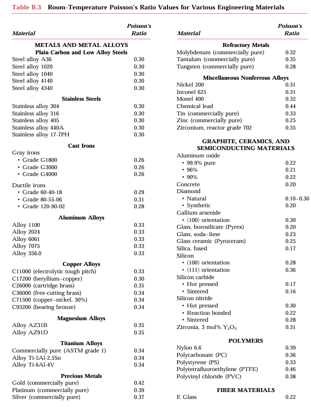
Table B.3. Room Temperature Poisson’s Ratio Values for Various Engineering Materials (Callister 448)
What It Takes to Move All That Weight
Using the right materials, design and aerodynamic profile are also important when discussing fuel and energy consumption. While there are new technologies that enable the powertrain—or the car’s engine, transmission, drive shaft, differentials, and axles—to be more fuel and energy efficient on its own, it’s also important for engineers to keep in mind everything around the powertrain can influence how much fuel and energy the car might need and, possibly, save. Let’s look at the different components of a car that have an impact on the supercar’s or hypercar’s fuel and energy efficiency.
If we take a look at the equation for kinetic energy:
KE = ½ * m * v^2
KE: Kinetic Energy
m: mass of supercar or hypercar
v: velocity of supercar or hypercar
(Note: The supercar’s or hypercar’s potential energy (PE) is stored in its fuel and/or battery system
Must be able to compensate for continuous powertrain output and inefficiencies in the supercar’s or hypercar’s powertrain)
…we can see how the supercar’s or hypercar’s mass is a major factor. Using lightweight materials is key for reducing the supercar’s or hypercar’s energy demands. Less energy demand could increase the supercar’s or hypercar’s driving range or time it lasts on the track. This is also a reason why OEMs would prefer to use monocoque chassis to make supercars and hypercars compared to a highly sophisticated space frame chassis (i.e. the Ferrari SF90 Stradale with a monocoque chassis weighs 3461 lbs while the C8 Corvette ZR1 with a space frame weighs around 3670 lbs).
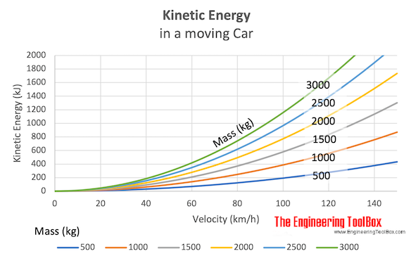
A graph showing the relationship between mass vs. kinetic energy (Image courtesy of The Engineering Toolbox)
Another factor influencing fuel consumption is the car’s aerodynamic profile. A higher C_D means that the car will need to overcome more force, requiring the engine to work harder and, thus, use more fuel (refer to the drag force and lift force sections of Going With the Flow for a refresher). This can be seen in the C8 Corvette ZR1, where the fuel efficiency of the ZR1 with the ZTK Track Package is less than the fuel efficiency of the ZR1 without the ZTK Track Package.
Another factor automotive engineers consider in fuel and energy efficiency are the car’s tires. As this article discussed in the Handling Life’s Twists, Bumps and Turns section where it discusses static friction, kinetic friction, and cornering stiffness, the main goal of the tires is to keep the car on the road as firmly as possible without sliding. Not only does keeping the car on the road keep the car planted, but it also reduces the car’s energy demand since the tires that keep the car on the road more directly transfer the power to the road, resulting in less energy consumed and wasted.
It’s quite a task to ensure a supercar or hypercar uses as little energy as possible, but it’s needed now more than ever. Governments and societies around the world are demanding that cars be more environmentally conscientious and reduce their negative impacts on the environment. Furthermore, fossil fuels are nonrenewable resources, meaning that when Earth runs out of fossil fuels, we can’t make any more. Even though it’s a challenge many don’t want the automotive industry to embark on, it’s one that’s desperately needed for the future of not just supercars and hypercars, but the automotive industry as a whole.
If you want to explore the properties of a common material, you can visit The Engineering Toolbox’s Material Properties webpage and find out more about it
Money Well Spent
None of a supercar’s or hypercar’s advanced technology and sophistication are free or cheap to make. They require considerable amounts of capital and time investment. Much of the decisions to use certain materials and builds come down to time and cost. Let’s see how these two variables are taken into consideration when designing and engineering different components of a supercar or hypercar.
Arguably one of the most important aspects of any car is its chassis. This is the part of the car that gives the car its structure and greatly influences its handling and driving dynamics as this article discussed at length in the Building From a Solid Foundation section. Ensuring the chassis not only meets the needs and demands of the customer but that construction and materials costs remain within budget constraints—a constant challenge for engineering teams.
Monocoque chassis, while lighter and more cohesive as a structural unit, require more complex building operations which most times can only be achieved through handwork methods. Not only does this mean greater time needed to complete, but also greater costs as human capital will be more expensive than machined labor that can be depreciated over time. This is a huge reason why cars such as the upcoming McLaren W1 and Ferrari F80 have such high price tags.
Space frame chassis, on the other hand, are heavier overall due to the various beams and tubes needed to construct it and the additional body panels needed as compared to cars with monocoque chassis. However, space frames can more effectively be made using machine labor, thereby reducing construction costs and build times. This is one of the reasons why cars such as the Audi R8 and C8 Corvette ZR1 are relatively much less expensive than other comparable performance cars.
As this article explored in the Handling Life’s Twists, Bumps and Turns section, some supercars and hypercars have a multi-link rear suspension and others have an SLA rear suspension. While the section did mention how engineers take into consideration the daily driving goals of the customer, another factor is cost. Due to the increased complexity of multi-link suspensions, they are generally more expensive to build and require more time to make them. While cars like the Ferrari LaFerrari and the Porsche 918 Spyder use multi-link rear suspensions based off the time and capital resources allotted to them during their production, cars such as the C8 Corvette and the Audi R8 did not have the same time and resources and, thus, chose to use SLA suspensions as their rear suspensions.
Other components, including wheels, springs & shocks, steering components, brakes, and aerodynamic elements, also contribute greatly to the supercar’s or hypercar’s assembly and manufacturing costs. It is why evaluating each part’s design and the effectiveness is so important. Many of these parts could possibly get overlooked and may be able to be produced cheaply for some time. However, this is not the best practice because this could also cause the company to recall parts and spend more time and money than needed to fix these issues.
Materials vary in cost based on availability or time and labor required to produce the material. This reality should be heavily considered when choosing the right material for each part. For example, cars such as the C8 Corvette use aluminum to build their space frame chassis, which costs less than the woven carbon fiber used in the monocoque chassis of cars like the McLaren W1 and is also a reason why there’s such a huge price disparity between the two cars.
Other materials such as titanium, magnesium and forged aluminum are generally considered premium materials and cost more, while forged carbon fiber is generally considered a cost-effective material due to its low labor costs and robust performance
Assembling Everything into One Piece
This article explores the complexities and engineering involved in everything responsible for making a supercar or hypercar dance across a windy road or racetrack while also being able to handle daily driving activities. Some of you might ask: “Why does this matter?” “Why should I care how they engineer supercars and hypercars? This will never affect me!”
Even though on the surface and in daily living the supercar or hypercar itself might not affect you, the lessons engineers learn from creating these masterpieces definitely impacts the way everyday cars are built in the future. For example, 155 mph in 1954 might have seemed like rarified air that only the Mercedes-Benz 300 SL Gullwing could only achieve; in 2025, many affordable used cars made for everyday folks can reach these speeds. The 2005 Bugatti Veyron’s massive 1,001 hp 8.0L quad-turbo W-16 engine was thought of as a technological marvel; twenty years later, Chevrolet—a manufacturer of everyday vehicles—managed to produce 63 more horsepower from a 5.5 L twin-turbo V-8—a smaller engine with half the turbos in the Veyron’s W-16, half the cylinders and over 31% less engine displacement overall—at a fraction of the cost (for reference, a fully loaded C8 Corvette ZR1 with the 5.5L twin-turbo V-8 costs less than $200,000 in 2025, while the Bugatti Veyron in 2005 commanded $1.25 million, or the equivalent of almost $2.1 million in 2025). While still expensive, it’s technology that was out of reach for 99.9% of the world and is now far more accessible than ever before.
Supercars and hypercars used SLA front suspension and multi-link rear suspension setups for years. Do you know what else used this setup? The 2008 Cadillac CTS. Why does this matter? Because this was the time when the global economy and GM were both beaten and bruised, and the CTS helped change the vision, direction and trajectory of Cadillac. It proved that Cadillac could compete with the best of the world, even if it wasn’t quite the Standard of the World yet. Nonetheless, it paved the way for future Cadillac models like the Cadillac Celestiq to truly go head to head with the best the world had to offer from the likes of Rolls-Royce and Bentley.

The Cadillac Celestiq, an American luxury car that can go head-to-head with Rolls Royce and Bentley (Image courtesy of General Motors)
You can also find this sophisticated suspension setup in everyday vehicles like the 2025 Ford Expedition and similarly in the 2025 Ford Explorer (the Explorer utilizes a MacPherson strut front suspension instead). Since more customers want a mix of utility and everyday driveability, SUVs are now incorporating this suspension setup. It might be the reason why these vehicles are becoming more expensive than they have been in the past, but it’s a far cry from the high prices that customers paid when they were used in supercars and hypercars in the past.
Just to help drive the point home even more: the 1984 Ferrari Testarossa was a supercar in every way. It had a 0-60 time of 5.2 seconds and a quarter mile time of 13.5 seconds. Motor Trend tested a vehicle in July of 2025 that could do 0-60 in 5.2 seconds and the quarter mile in 13.8 seconds. Do you know what vehicle that was? The 2025 Ford Explorer ST. A modern vehicle that can transport your husband, wife, partner, kids, grandma, your auntie, your favorite pets, and everything else can hold its own against a Ferrari made in 1984. Just think about that for a moment.

A 2025 Ford Explorer ST proving it can hold its own against the 1984 Ferrari Testarossa (Image courtesy of Hearst Autos, Inc.)
So, no, supercars and hypercars are not trivial machines only for the elites of the world. They are meant to point the world toward what’s possible for the future of engineering behind the cars everyday Joes and Jills will drive. They are meant to push the boundaries of what’s possible today to show us what’s in store for the rest of us in the future.
Even though you might not want to own a supercar or hypercar, hopefully you understand the complex engineering that goes on behind the scenes and how it can affect everyone in the future. With that said, how can we preserve the mystique around the hypercar and advance the world of engineering? Can hypercars exist in the future with the current challenges around transportation? How can we make the technologies exhibited in these cars cheaper so that they can benefit everyday folks who just want to enjoy safe and reliable driving more? Let us know in the comments below!
Additional References:
Callister, William D.. Fundamentals of Materials Science and Engineering: An Integrated Approach. 5th ed., John Wiley & Sons, Inc., 2001.
Gillespie, Thomas D. Fundamentals of Vehicle Dynamics. SAE International, 2021.
Katz, Joseph. Automotive Aerodynamics. John Wiley & Sons, Ltd., 2016.
Get a quick dose of inspiration from Unifunful Today here
See our thought-provoking articles from Everyday Engineering here and investigate the engineering behind everyday items and places
See more articles from Engineering in Motion here to see how engineering moves us around the world
Missed last week? No worries, we got you! See what we covered last week and more in our weekly status reports here
Discover the vision and values guiding the Unifunful mission here
First time visiting Unifunful? Become familiar with the history and foundation Unifunful was built on here
Meet the contributors who make Unifunful possible here