

Old School Heart with New School Brains
From the early days of the automobile up to now, one thing has remained constant throughout time: the powertrain being the heart of the machine. The marrying of an engine to a frame is what made the first automobile—which many consider to be the Benz Patent Motor Car, model no. 1 invented by Carl Benz—possible. This was a revolutionary feat on January 29, 1886 since the world was powered by horse-drawn carriages. An improved version of this invention would go on to demonstrate how reliable gas-powered cars can be as Carl Benz’s wife, Bertha, and her two sons, Eugen and Richard, would drive 180 kilometers from Mannheim, Germany to Pforzheim, Germany.

The Benz Patent Motor Car, model no. 1 (Image Courtesy of Mercedes-Benz Group AG)
Automotive engines would improve over time and become more powerful and efficient, especially as consumers craved more speed. This is evident with the creation of the 1914 Vauxhall 25hp ‘Prince Henry’ Sports Torpedo, which many consider to be the world’s first sports car. By 1931, the car’s original owner completed 140,000 miles from the numerous tours he completed. In just a 45 year time span from when the automotive world started with the Benz Patent Motor Car, model no. 1, the motor car went from a machine that could travel 180 km (111.9 mi) to over 140,000 mi.
From the company which brought the first car to the world came a car that would again revolutionize personal transport in the form of another world first: the supercar. This would be achieved with the creation of the 1954 Mercedes-Benz 300 SL Gullwing. The Gullwing was able to reach a top speed of 155 miles per hour (mph), or 250 kilometers per hour (km/h) and was the fastest production car of its day thanks in large part to its 220 hp inline 6 engine.

Mercedes-Benz 300 SL Gullwing (Image courtesy of Mercedes-Benz)
The 300 SL Gullwing’s reign, however, was not to be forever as the 1966 Lamborghini Miura would claim the crown with a top speed of 174 mph (280 km/h). This was in large part due to the Miura's aerodynamics and also its 350 hp V-12. As one can imagine, this engine was cutting edge back in 1966 as most engines were not able to produce this much power.
Only eight years later, the 1974 Ferrari 365 GT4 BB would claim this crown having a top speed of 186 mph. It didn’t hurt that it was built with a 4400 cubic centimeter V-12 that could produce 380 hp. Just as the Lamborghini Miura before it was displaced, so too would be the Ferrari 365 GT4 BB. I detail the saga of how engines and other aspects of automotive technology in supercars and hypercars kept advancing up to the modern day in the introduction of The Art of Mastering Driving.
Even as these cars advanced, the essence of the internal combustion engine (ICE) hasn’t changed. Newer cars such as the Rimac Nevera and Rimac Nevera R are incorporating fully electric powertrains. Others such as the Ferrari F80 incorporate a hybrid powertrain system, or a combination of an ICE and electric motor(s), to capture the best of both worlds: the drama and power of an ICE along with the efficiency of an electric motor.
How has the ICE evolved from its early days in the Benz Patent Motor Car, model no. 1 to the present day? How do electric motors work and what keeps them going? These are some of the questions which lie at the heart of this article and ones that this article will hope to demystify. With that said, let’s begin to understand the main components behind the heart of any supercar or hypercar: the powertrain.
Forming a Perfect Union
Breathing it In
When it comes to dealing with ICE powerplants, it’s important to understand that in order for these cars to work, one of the first things that engineers must solve is the supercar’s or hypercar’s air/fuel mixture. This is critical for the supercar’s or hypercar’s engine to work at optimum efficiency. The air comes into the engine from what is called an air intake pipe, which is a tube made usually from plastic, carbon-fiber, or aluminum connecting the engine intake to the air from the environment. Near or at the front of the air intake pipe is an air filter to help separate very small impurities found in the air.
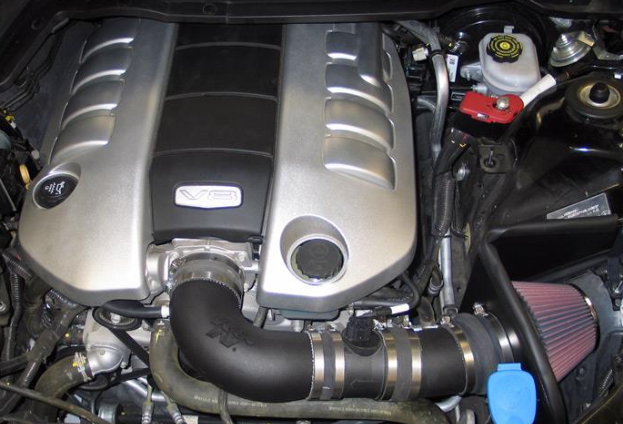
Here is an image of a typical air intake pipe like the one from K&N (large black pipe in image) which directs air from the air intake filter (pinkish cone at bottom right of picture) to the air intake manifold (underneath plastic engine cover sitting on top of the engine block) (Image courtesy of PTUNING.com)
How is this achieved to best optimize engine performance? Well, it is managed through the car’s Engine Computer Unit (ECU) by optimizing the flow rate, or how quickly a fluid such as air moves through a particular cross section of an enclosed or defined space. Here’s the formula which governs this phenomenon:
Q = V * A, where:
Q = Volumetric Flow Rate (ft^3/s or m^3/s)
V = Velocity of fluid (ft/s or m/s)
A = Cross-sectional area (ft^2 or m^2)
The optimal flow rate is determined during the engine’s testing and development. When finalized, the information is stored in the supercar’s or hypercar’s ECU which will then regulate the flow rate of the air coming into the engine.
Once the air completes its path through the air intake, the air is funneled to each of the engine’s combustion chambers via an air intake manifold. The air intake manifold is an engine component which connects to the end of the air intake pipe and is mounted on top of the engine block. To ensure air doesn’t escape from the air intake manifold, the air intake pipe end connected to the air intake manifold is usually clamped to the air intake manifold opening while the section of the air intake manifold connected to the engine block is usually sealed via a rubber or metal gasket. This ensures the system is air tight and that the engine receives as much air as possible.
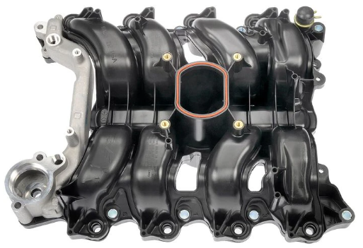
This Dorman Intake Manifold is a typical example of how an air intake manifold is designed and built (Image courtesy of AutoZone, Inc.)
The Energetic X Factor
The air from the environment is not enough to power the engine. The engine needs a fuel source that can provide enough energy to generate a sufficient amount of power to propel the car. In the context of ICE powerplants, this fuel source is either called gasoline or diesel.
This fuel is stored in the car’s fuel tank and is transported from the fuel tank to one of the engine’s combustion chambers via a fairly straightforward fuel system. The fuel pump draws fuel from the fuel tank via the fuel line into the combustion chamber. Just like in the air intake system, the fuel is filtered through a fuel filter before it enters either the carburetor or a fuel-injection system.
Even though both a fuel injector and a carburetor serve the same function, which is to direct fuel towards the combustion chamber, the two are very different in their operations. With a carburetor, the process is 100% mechanical and relies on a float meter to control the flow rate of the fuel into the intake port or manifold leading to the combustion chamber. Even though the carburetor is simpler to engineer and build, these components are not as accurate as fuel injection systems are. This is why Original Equipment Manufacturers (OEMs) don’t use these in modern day supercars and hypercars.
Fuel injection systems, on the other hand, are much more accurate and regulate the flow rate of the fuel via the car’s ECU. These systems spray fuel into the car’s intake ports or manifold based on inputs received by the ECU versus a more mechanical and simplified float. Many modern day supercars and hypercars use a direct fuel injection fuel system, which injects fuel directly into the combustion chamber via small jets and is also regulated by the car’s ECU. Even though they are more accurate than carburetors, they are more complex due to their mechanical nature and are generally more expensive.
Regardless if the hypercar or supercar uses fuel injection or a carbureted system, it is always important to understand which kind of fuel will work best with each car’s powertrain. This is where OEMs create recommended gasoline fuel ratings based on the supercar’s or hypercar’s desired engine performance. These fuel ratings—such as Regular, Plus and Premium in the U.S.—are based on the combination of pure iso-octane (2, 2, 4, trimethylpentane) and n-Heptane.
Iso-octane carries an octane rating of 100, while n-Heptane carries an octane rating of 0. The more iso-octane the fuel has the higher the octane rating. For example, unleaded regular gasoline in the U.S. has an octane rating of 87, which means it acts like a fuel that contains 87% iso-octane and 13% n-Heptane, not that it actually has that same proportion. OEMs like to engineer engines made for mass-produced cars to run on 87 octane fuel to create a more affordable car for the customer and, thus, help drive sales. For more premium vehicles which require a higher amount of compression in the combustion chamber, the OEM might prescribe a higher octane fuel for the engine.
Some professional race cars require specialized fuel known as racing fuel. These fuels are interesting in that they have an octane rating higher than 100. This is because, on top of the fact that the fuel contains high levels of iso-octane, the fuel contains additives which boost the octane rating above 100. Many of these additives are toxic and cause the racing fuel to be leaded, and both pose risks to both the environment and human health. Because of this fact, it is illegal to use racing fuel in many countries around the world.
Unleashing a Powerful Cycle
Once the fuel is evaporated from liquid to gas and mixes with the air from the air intake system in the combustion chamber, the air is then compressed via a piston inside the combustion chamber. Depending on the fuel that was used, it will create a compression ratio inside the combustion chamber. It is important to understand what a compression ratio is in order for an engine to operate properly.
As mentioned in the previous section, understanding which type of gasoline will allow the engine in a supercar or hypercar to run at optimal performance is paramount. Using a cheaper fuel that has a lower octane rating may result in decreased power or, worse yet, knock. Knock is when fuel randomly combusts in the engine’s combustion chamber(s) and can create pressures that far exceed what the engine was originally designed to withstand. Issues that can potentially arise from knock include: destroyed pistons, cracked engine blocks, bent crankshafts, ultimately leaving the engine permanently destroyed. Depending on the engine, this could total the car and render it beyond repair.
This is why the ideal gas law equation is so important to learn and understand, especially when designing and engineering engines. For those who forgot that equation, here it is:
PV=nRT, where
P: Pressure (lb/ft^2 or N/m^2 (Pa))
V: Volume (ft^3 or m^3)
n: number of moles (or 6.02 * 10^23 fuel molecules) in gas
R: Universal Gas Constant
8.314 kPa * mol / kmol * °K; 10.7316 psia * ft3 / lbmol * °R
T: Temperature (°K, °R)
Automotive engineers who work on engine design and performance utilize these parameters, even if they mainly use software to help calculate these values. Understanding the pressure, volume and temperature of the engine will greatly influence what the octane rating of the engine will be in order to prevent knocking.
Withstanding the Pressure of It All
More realistically, automotive engineers most likely utilize the relationships between pressure and volume (P-v) as well as temperature and entropy (T-s) during engine design and development. These values help engineers better understand compression ratios as well as heat generation, all of which are vital when considering engine cooling and optimal fuel type. These two different relationships are demonstrated through the P-v Diagram and also the T-s Diagram and can tell the engineers how the engine responds at certain phases of the engine cycle. This article begins by analyzing the P-v Diagram and the implications that arise from understanding how pressure and volume change in an engine’s combustion chamber.

Above is the isentropic Pressure vs. Volume (P-v) Diagram for an Otto cycle engine. For those who are not familiar with an isentropic process, here it is: a process that doesn’t have any inefficiencies—also known as irreversibilities—and doesn’t allow heat to transfer through the engine to its outer environment. The different points of the graph are also different stages of the compression cycle. Furthermore, the arrows which show the direction of qin and qout show where heat (q) is coming into the cycle (q_in) and out of the cycle (q_out).
For context, here are what the different points on the P-v Diagram represent: 1) empty combustion chamber ready for air/fuel mixture intake 2) combustion chamber filled with air/fuel mixture 3) air/fuel mixture compressed in combustion chamber 4) combusted gas released from the combustion chamber via the exhaust valves. Furthermore, the arrows in the direction of the cycle and how pressure and volume change within the combustion chamber during the duration of the gas cycle.
The direction of the arrows signify these different processes taking place: From 4 to 1: exhaust gases from the internal combustion process are released via the exhaust valve; from 1 to 2: new air/fuel mixture in the combustion chamber is compressed; from 2 to 3: spark from the spark plug creates greater entropy and, as a result, greater pressure in the combustion chamber; and finally from 3 to 4: the volume inside the combustion chamber expands as a result of the combustion initiated from the spark plug. The process then repeats itself from 4 to 1 and continues the cycle until no more fuel is available to continue this process.
Artfully Breathing In and Out
It’s interesting how a mechanical unit such as an internal combustion engine (ICE) can have so many moving parts when it’s a stationary unit in and of itself, but how do the volume and pressure change? What makes it operate in such a cyclical way? The answer lies in the piston moving within the engine’s combustion chamber.
The engine uses the power from the chemical reaction of the fuel/air mixture exploding in the combustion chamber to create a force which pushes on a component within the combustion chamber known as a piston. The piston, depending on where within the Otto combustion cycle it’s in, can be in its highest position within the combustion chamber where the air/fuel mixture is compressed the most—known as the Top Dead Center (TDC)—or can be in its lowest position—known as the Bottom Dead Center (BDC). Below is an illustration showcasing both TDC and BDC:

Figure 1: Diagram showing a piston at Top Dead Center (TDC)

Figure 2: Diagram showing a piston at Bottom Dead Center (BDC)
Tested In Fire
Along with the P-v Diagram analyzed in the previous section, engineers also utilize a temperature (T) and entropy (s) diagram (T-s Diagram) to help understand the ICE powerplant’s behavior. Understanding how the engine’s temperature and entropy, or the random disordered movements of the air/fuel mixture particles within the combustion chamber, affects its overall performance is essential for understanding the engine’s potential long-term reliability and durability under various loads. The T-s Diagram below showcases the relationship between temperature and entropy in an ideal Otto cycle engine. For those who wish to know more about entropy, visit this section in Pushing Out Heat to Keep Refrigerators Cold.
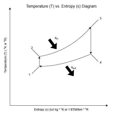
As in the P-v Diagram, there is heat coming into the system (q_in) and heat going out of the system (q_out). The numbers in the T-s Diagram represent the same thing the numbers in the P-v Diagram represent. What’s different about this diagram compared to the P-v Diagram is that the arrows represent what happens with the heat rather than the pressure. Here’s what the diagram illustrates: from 4 to 1 represents constant-volume heat rejection; from 1 to 2 represents isentropic compression; from 2 to 3 represents constant-volume heat addition; and finally from 3 to 4 represents isentropic expansion.
An Ideal versus The Reality
Unfortunately, as with all things in life, this process isn’t without its inefficiencies, or irreversibilities. The process is not adiabatic where heat is perfectly kept within the combustion chamber. There is also friction between the motor oil and the piston due to the shear stress within the motor oil as a result of it being between the cylinder wall and the piston, adding more heat loss from the system.
Does this mean that the ideal P-v and T-s diagrams in this article are null and void? Not necessarily. While the ideal and actual P-v and T-s diagrams most likely differ in their presentations, the two compliment each other in that both diagrams keep generally the same shape.
The difference is the actual diagrams showcase the irreversibilities in the real-world process while the ideal diagrams don’t. However, since the ideal diagrams are easier to read and understand while also showing what the engine can possibly achieve, they are the diagrams most used to explain thermodynamics in ICE powertrains and also help engineers benchmark engine performance. These P-v and T-s diagrams help engineers design the ICE powerplant’s pistons, which are the components that bring the engine to life.
The Power of Two
Some engines only need the pistons inside their engines to make one complete vertical movement from TDC to BDC to bring in the air/fuel mixture through the intake port and release exhaust gases from the exhaust port. The piston in these engines will then travel from BDC to TDC to both compress the air/fuel mixture (compression) and prepare the mixture for a spark from the spark plug (ignition). These engines are known as two-stroke engines and the vertical movement of the piston in the combustion chamber is known as the stroke. Here’s an example from Engineering Explained’s Jason Fenske which explains the two-stroke process in more detail.
Not many cars have two stroke engines and are more common in motorcycles and dirt bikes. Nonetheless, original equipment manufacturers (OEMs) have attempted to place these engines into road-going cars. Here’s a list of some road-going cars that have used two-stroke engines.
The Favorite Quartet
The overwhelming majority of cars, however, don’t have two-stroke engines but instead have four-stroke engines. There are two more strokes in the process, but it is more efficient than a two-stroke process. Below is how a four-stroke engine works (you can see Jason Fenske explain it more here):
Intake Stroke: Piston moves from TDC to BDC in combustion chamber; draws in air/fuel mixture
Compression Stroke: Piston moves from BDC to TDC in combustion chamber; compresses air/fuel mixture
Power Stroke: Piston moves from TDC to BDC in combustion chamber as a result of combustion; turns car’s crankshaft through connecting rods
Exhaust Stroke: Piston moves from BDC to TDC in combustion chamber; exhaust gases from combustion reaction released from combustion chamber
Due to the nature of ICE powerplants and how they operate, the more pistons that can convert chemical energy into mechanical energy is ideal. More pistons apply more torque on the crankshaft by applying a force at an optimal distance away from the center of the car’s crankshaft. This is why many supercars and hypercars usually have large 8-, 10-, or 12-cylinder engines or even more that manage to make the crankshaft generate 8,000 to 10,000 revolutions per minute like this Lexus LFA. This article will discuss later on how crankshaft and overall engine design greatly influence engine performance.
A Sixth Dimension?
As any top-tier manufacturer will do, Porsche is innovating engine performance. They have recently patented a six-stroke engine design that could potentially be used in future vehicles. Here’s Jason Fenske on Engineering Explained explaining how this new engine will work.
Could this engine find its way in future supercars and hypercars? Only time will tell, but if Porsche has patented this technology, there’s a good chance it could definitely happen. Some say this could be a response to the ongoing electrification of supercars and hypercars, but whatever the reason may be, this can definitely raise the standard in supercar and hypercar performance.
Having Just the Right Spark
Regardless if the gasoline engine is two-stroke, four-stroke, or even six-stroke, high compression in gasoline engines is not enough to make the fuel/air mixture in the combustion chamber combust or explode. In supercars and hypercars, these engines require components known as spark plugs that send just enough electric spark into the combustion chamber when the mixture is compressed to allow combustion to occur. However, similar to how not all engines have the same compression ratios and require fuels with different octane levels, the same can be said for spark plugs. Here’s a wonderful article from AutoZone which explains in detail which spark plugs work best for each type of vehicle and why.
Neither Too Hot Nor Too Cold
From Hot to Cool
Regardless of which gasoline-powered ICE powerplant is inside each supercar or hypercar, these engines generate great sums of heat due to the high compression, the high rpms, and the sparks generated inside these engines. As a result, these engines generate too much heat to not be engineered with efficient cooling systems. Many of the metallic and polymer-based components used to construct the engine would fail if the temperature was left unregulated.
Why can’t ICE powerplants keep this heat within their combustion chambers and only release the heat via their exhaust pipes or utilize the energy to be converted to mechanical energy? This is because in combustion, heat will always be generated and according to the latest science and engineering available as of the writing, there is no way to convert heat into usable energy. Furthermore, with a system like an ICE powerplant, the heat will move through the car’s engine block or metal exhaust pipes through a process known as heat transfer. Here are a couple formulas that show how heat transfer works:
q”=k((T_1-T_2)/L)
q”: Heat flux (W/m^2)
k: conductivity constant (W/(m*Kelvin))
Specific to each material
T_1: temperature at x=0
T_2: temperature at x=L
L: thickness of material heat is being
transferred through (m)
Before explaining heat transfer, it is important to understand what heat flux (q”) is, which can be defined as the amount of heat that can transfer through a specific material for any unit of area. In other words, it's how much heat can travel through either a thin or thick section of material. This is measured by understanding what type of material the heat is being transferred through (where the constant k comes in), the difference between the beginning temperature (T1) and the end temperature (T2), and the thickness of the material (L).
Now having an understanding of heat flux, here is what heat transfer is in mathematical terms:
q=q”*A
q: Heat Transfer (W)
q”: Heat Flux (W/m^2)
A: cross-sectional area (m^2)
As the formula suggests, heat transfer is how much heat flux occurs through a defined area. Understanding this concept is crucial for automotive engineers in order to design and engineer effective cooling systems for the ICE powerplants they are creating. Here are two common cooling systems that have been used to regulate temperatures in ICE powerplants over the years.
A Cooling Breeze
IIn the early days of automotive engineering, some engines in cars were cooled by air. The idea is that the faster a car drives, the more air will flow over the engine and will correspond to the amount of cooling the engine will need. This type of engine is known as an air-cooled engine, where the air cools the car’s engine. Figure 3 illustrates how this process works:
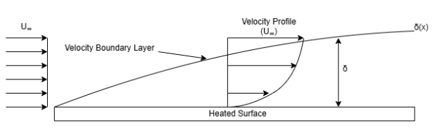
Figure 3: Velocity Boundary Layer Diagram
As shown in Figure 3, air (U_∞) moves over a heated surface. The more the air particle moves along the heated surface, the further away it moves from the surface and creates what’s known as the velocity boundary layer (δ(x)). As the air particle moves further away from the surface, the greater its velocity is as shown in the velocity profile due to the air particle being subjected to less shear stress. Moreover, the greater the distance is between the air particle and the heated surface (δ), the less effect the air particle has on cooling the heated surface. If the air particle has a δ that is greater than or equal to the corresponding velocity boundary layer value at any particular point, then the cooling effect of the air particle is negligible.
Understanding air cooling via Figure 3 is crucial to engineering air-cooled engines. This is also why many older motorcycles are built to have their ICE powerplants exposed to the environment. Many of these older motorcycle engines have ribbed external protrusions along their engine blocks. Why is that? It’s because those external protrusions, or fins, are an enhancement to air-cooling issues earlier engines faced. Figure 4 will examine this phenomenon in more detail.

Figure 4: Actual (q_f) and maximum (q_max) heat transfer in a ribbed fin
As shown in Figure 4, fins allow more heat to be transferred from the engine due to greater surface area. Depending on how much heat is actually transferred to the fin (q_f) in relation to how much heat the fin can transfer (q_max) will determine how efficient the fin is. Here’s how the fin’s efficiency can be measured:
Ƞ_f = q_f / q_max = q_f / [h * A * (T_b-T_∞)]
Ƞ_f = fin efficiency
h= convection coefficient (W/(m^2 * °K))
based on fin material
A=cross-sectional area of fin (m^2)
Since this is an air-cooled system, the maximum heat transfer (q_max) is determined by the convection coefficient (h), the cross-sectional area of the fin (A), and the difference in temperature from the fin’s base (T_b) to the tip of the fin (T_∞). As with most machines, ensuring q_f is as close to q_max as possible to get Ƞf to be as close to 1 is the main goal for air-cooling systems on engines.
Unfortunately, many engines are enclosed in an engine bay in an effort to maintain a supercar’s or hypercar’s aerodynamic profile as explained in The Art of Mastering Driving. Furthermore, some supercars and hypercars have engines that generate far too much heat on their own even with adequate exposure to the outside environment for an air-cooled process to be effective. If this is the case, how does the engine stay cool under extreme conditions? How is heat transferred away from the engine? This is where radiators and radiator systems come into play.
Quenching the Heat
As stated previously in the last section, modern-day ICE powertrains found in supercars and hypercars generate much more heat than engines that solely rely on air cooling. These cars are not able to be effectively cooled only by air flow over the engine block, or the structural component of the engine where the pistons, connecting rods and crankshaft reside. They need assistance from a cooling system consisting of a radiator, radiator fluid, a radiator pump, and hosing to connect the system to other parts of the engine, and also the heater core (used as the car’s heater during cold months).

Figure 4: Typical diagram of engine cooling system
The coolant—both cooled and heated—in Figure 4 circulates through a series of radiator hoses between the radiator and engine block and through heater hoses between the heater core and engine block. Inside the engine block, however, the heat is transferred from the engine block in metallic pathways to the coolant in a similar fashion that heat is transferred from the combustion chamber to the fins on air-cooled engines.
This is in part due to the Second Law of Thermodynamics, which states heat transfers from an area of high temperature to an area of low temperature. When the coolant leaves the engine block, it is transferred to the engine’s thermostat, a mechanical component which regulates engine temperature via regulating fluid flow of the coolant. The coolant then flows to the radiator where the radiator fan expels the heat the coolant collected from the engine bay into the environment. Once cooled, the coolant recirculates through the system to repeat the process.
In more modern systems, however, radiator coolant flow is governed by an electric thermostat which relays information such as coolant temperature back to the engine control unit (ECU) that accurately regulates coolant flow through the engine. Another component to modern cooling systems is the coolant reservoir. This is a storage compartment for the coolant within the cooling system as it expands due to thermal expansion.
Things are not always black and white when it comes to engine cooling mechanisms. For supercars and hypercars that contain high-revving engines, or engines whose crankshafts turn at over 8,000 rpms, they utilize both cooling systems with radiators and air cooling. Common examples include the C8 Chevrolet Corvette ZR1’s cooling system and front radiators and the Aston Martin Valkyrie’s cooling system with two radiators and rear air vents to help cool its 6.5 L V-12 that screams to over 11,000 rpms! So, even though more modern cars utilize engine cooling systems, other cars such as supercars and hypercars blend the two due to the much greater amounts of heat generated by these engines.
Behind the Mechanical Heartbeat
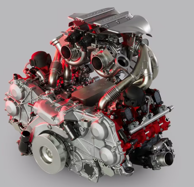
The 3.0 twin-turbo Ferrari V-6 powering the Ferrari F80 (Image courtesy of Ferrari S.p.A.)
Holding Everything Together
For an internal combustion engine (ICE) powertrain to perform its function effectively, it must rest on a solid structural foundation—one that connects all components while withstanding the high temperatures and pressures of combustion, the shear stresses from the oil as a result of the movement of the pistons and crankshaft, and the normal stresses as a result of the screws that are used to build the engine while also ensuring the ICE powertrain’s gaskets are air tight (see The Art of Mastering Driving for detailed explanations of shear stress and normal stress). Furthermore, this structural foundation must be constructed in a way that does not add too much weight to the supercar or hypercar. Even though this component never moves, or is static, it must withstand all the heat, pressure and expectations that are placed on it without cracking or exploding.
This component of the engine is known as the engine block. From the standpoint of supercars and hypercars, these components are made from various aluminum alloys, which are known for their lower density and weight and higher yield strength, or how much the metal comprising the engine block can resist bending and deformation. The combustion chambers the pistons reside in are milled, or drilled with a circular bit, to a certain diameter at a particular depth based on the specifications — a detailed list of dimensional, material, and performance requirements — of the engine.
Since supercar and hypercar engines produce large sums of heat, these engine blocks will also be designed with channels for the coolant to move through. Their designs must also ensure that motor oil, either petroleum based or more commonly synthetic in supercars and hypercars, can flow between the moving metallic components. This is crucial to prevent excessive kinetic friction between the moving parts and the engine block’s surfaces, extending engine life and maintaining performance.
In supercars and hypercars, motor oil can also be used alongside the engine coolant as a second engine coolant to regulate the engine’s temperature. This is due to a technological innovation known as a dry sump system that allows the motor oil to cool and transfer some of the heat from the engine away from it. MotorTrend has a wonderful article which explains this process in more detail.
The Driving Force Behind the Beat
Inside the combustion chambers of the engine block are mechanical components called pistons. This is the part of the engine which converts the chemical energy from the combustion reaction to mechanical energy. Just like the engine block they reside in, the pistons in supercar and hypercar engines are made from aluminum alloys for the same reasons the engine block is made from aluminum alloys. To ensure the engine’s crankshaft achieves optimal performance, the firing order of the pistons is essential and must be carefully calibrated.
Although they are simple in their operation, they are vital for optimal engine performance. Because of this fact, the tolerance—the difference in the designed measurements of the pistons compared to the actual measurements of the manufactured pistons—given to the pistons is usually less than 0.01”. This is to ensure the pistons keep both the fuel/air mixture and exhaust gases in their combustion chambers. Pistons are also made with seal rings and oil scrapers to assist with this. Here is a parts schematic of a Ferrari Enzo’s piston/connecting rod assembly to help illustrate how they are designed and manufactured.
Connecting to the Force
As the piston is converting the chemical energy from the combustion reaction to mechanical energy in the form of the piston stroke, it is also pushing on a vertical rod which transfers the mechanical energy from the piston to the crankshaft. This component is called a connecting rod and can be seen in the same parts schematic used to view a Ferrari Enzo’s piston design. Even more simple than the piston, the connecting rod directly spins the crankshaft responsible for powering the supercar’s and hypercar’s transmission, which will be discussed in another article. In an effort to save as much weight as possible, original equipment manufacturers (OEMs) may construct the engine’s connecting rods out of titanium as well as the aluminum alloys they used to create the engine block and pistons.
Powering the Movement
As this article has alluded to, the crankshaft is the culmination of the mechanical power relayed from the engine’s pistons to the connecting rods connected to the crankshaft itself. It is this component that makes the engine such a valuable machine to the hypercar and supercar experience. However, the crankshaft is not made as a straight shaft but rather a set of offset shafts connected by metal bars. The offset design directly correlates with the firing order of the crankshaft and also to ensure the crankshaft never causes the engine to become unbalanced.
Since the crankshaft transfers all the mechanical energy from the combustion chamber to the supercar’s or hypercar’s transmission, the material used to make the crankshaft needs to withstand all the forces that come from the connecting rods. One material which is able to handle such extreme forces while still handling the engine’s high temperature is billet 4340 steel. It has a high tensile strength, which means it's a metal that can withstand some of the highest normal stresses before it begins to bend. When it comes to supercars and hypercars that are made to deliver both extreme performance and everyday drivability, OEMs favor and prioritize materials like billet 4340 steel.
Due to the crankshaft’s offset shape, the crankshaft makes a journal bearing with the engine block. The way journal bearings work is that a smaller circular object rotates within a larger hollow circle. Figure 5 shows how this works for a crankshaft in more detail.

Figure 5: Diagram of Crankshaft Journal Bearing
While simple in their operation, the designing, engineering and manufacturing that goes into making crankshafts is no small task. They need to withstand high temperatures and loads, ensure the engine stays balanced while they spin at thousands of revolutions per minute (rpms), and ensure the rotation is in sync with the firing order of the engine’s pistons. Nonetheless, it's a wonderful demonstration of precision engineering in the simplest of contexts.
Breathing Like a Fine Swiss Watch
Timing is Everything
Just as the crankshaft has to keep in sync with the timing of the combustion chamber firing, so too do the components which regulate the fluid/air mixture intake as well as the exhaust fumes from the engine. The timing for these components is regulated by the engine’s camshafts. Camshafts, along with the valves and springs that use spring force to keep the valves closed, are usually stored in the engine’s cylinder heads. Once the camshafts and intake/exhaust valves are in place, the cylinder heads are mounted on top of the engine block via torqued screws and a series of rubber/metal gaskets to prevent leakage of air and oil from the engine.
It is of utmost importance that the camshaft is perfectly timed and enables the right amount of lift—how much either the intake or the exhaust valves open—to when the car’s exhaust and intake valves need to open. If the timing or lift is even slightly off, it could lead to major issues that could severely damage or even turn the vehicle into a total loss. This is why it is important to have vehicles inspected and serviced regularly by trained individuals who understand the different tolerances and specifications between different vehicles. Just to demonstrate how defective camshaft performance can affect overall performance, here is a video demonstrating the effects of a malfunctioning camshaft in a car.
Upon observation of a camshaft’s structure, it becomes apparent that, similar to the crankshaft, a camshaft has external protrusions from its center as well. It also operates as a journal bearing just like the crankshaft does in the crankcase. However, these protrusions are very different from the ones seen in a crankshaft. These protrusions are called camshaft lobes and are either directly or indirectly involved with the opening and closing of the intake and exhaust valves, depending on how the engine is manufactured. Here is an excellent source showing the different components of the camshaft and how they operate.
Depending on what the desired goals of the engine are and what kinds of budget constraints are in place can determine how the camshafts are built and placed in the engine. Some camshafts are constructed from one piece of metal—most likely a steel alloy—for long-term durability and lower manufacturing costs. Others are pieced together using multiple parts to ensure maximum timing precision and the ability to save weight on some components of the camshaft like the lobes.
Some engines are built with camshafts inside the engine to reduce costs. Others are built on top of the engine block to ensure timing precision and greater intake/exhaust control. So, even though camshafts have the same mission in all cars—to regulate intake and exhaust flow—they do so in completely different ways. This is especially so when comparing supercars and hypercars to mass-produced automobiles.
Regulating from Within
The cheapest and most simplistic type of camshaft/valve construction is what’s called a pushrod, or overhead valve (OHV), setup. In this setup, the engine’s camshafts are built into the engine and are directly connected to the engine’s intake and exhaust valves. While not as efficient as the camshaft operation that occurs in another engine’s cylinder heads, this operation is usually very robust and durable since the camshafts in these engines are usually made from a single piece of steel alloy.
These engines are common in cars that are more affordable, older, and in many muscle cars like an old Chevrolet Camaro SS or an old Plymouth Barracuda. These engines, however, are rarely seen in modern-day supercars and hypercars due to the immense demands and expectations that are placed on the engines that power these cars. While they are great for old-school muscle, they do not handle the dynamic driving conditions as well as other camshaft setups do, which is why Chevrolet switched from a pushrod setup in the C7 Corvette to a more modern, dual overhead camshaft setup.
Controlling from Above
Another type of camshaft setup is called a single overhead camshaft (SOHC) setup. This is where one camshaft is placed in each engine’s cylinder head and controls the movement of the rocker arms that control the opening of the valves and the springs connected to the valves close them. It’s a cheaper alternative than a dual overhead camshaft setup and more precise than a pushrod engine, but not as precise as a dual overhead camshaft setup is. This type of engine setup is not as common anymore as dual overhead camshafts are more commonplace in the automotive industry than in years past. An example of a SOHC engine is the V-6 offered in the 2016 Honda Accord.
In terms of the internal combustion engine (ICE) powertrains that are used in supercars and hypercars, they rely on a dual overhead camshaft (DOHC) design. DOHC engines consist of two camshafts in each cylinder head—one responsible for the intake valves and the other responsible for the exhaust valves. Furthermore, due to the nature of the supercar and hypercar’s intended function, weight is saved as much as possible and so much so in the car’s camshafts.
They are assembled as individual pieces, with the camshaft lobes being made from lighter materials that can still withstand high temperatures, stresses, and forces. Because of this, they ensure timing is accurate and precise, but also drive up costs as a result of increased labor. One example is the iconic 2005 Ford GT with its 5.4 L supercharged DOHC V8 which was a key ingredient to the Ford GT’s success against far more expensive European offerings. Furthermore, many of these cars utilize variable valve timing (VVT) to regulate their camshafts and are controlled by the car’s ECU. This mechanism allows the engine to maximize precision and timing of the lift in either the intake or exhaust valves.
Keeping Everything Air Tight
Although these components have not evolved much since the early days of the automobile, valves are still crucial in terms of overall engine performance. They are the gatekeepers of the engine’s intake and exhaust flow. Furthermore, they must be designed to such small measurement tolerances to prevent either the air/fuel mixture from entering the combustion chamber too soon or the exhaust gases to leave the combustion chamber before the explosion. Both scenarios can result in greatly reducing or having no compression in the engine’s combustion chamber.
This is also an area where engineers tend to save weight by creating intake and exhaust valves from metals such as titanium or forged aluminum. They can withstand the heat from the combustion reaction and also the forces exerted on them from either the springs, rods, rocker arms, or camshafts themselves. Nonetheless, while simple in design, engine valves must be able to execute their function seamlessly with almost no room for error. This, along with the machining and measuring required to make the camshafts and other timing/lift components just right.
Cleaning the Heat
Letting Off Some Steam
Once the air/fuel mixture is combusted and leaves the combustion chamber via the exhaust valve, it leaves through an exhaust pipe which is connected to the engine’s exhaust manifold. The exhaust manifold collects the exhaust gases that then travel down through the exhaust pipe. They can be either separate pieces or made as one unit from the same material. The material is usually a steel or aluminum alloy similar to what engineers use to make the engine block. Only carbon dioxide and water should be coming out of the exhaust pipe since the combustion reaction is the following:
Fuel Source + O_2 = CO_2 + H_2O
Unfortunately, this is not how it works in the real world. The fuel used to power supercars and hypercars usually contains carbon monoxide (CO), hydrocarbons (HC) and various nitrous oxides (NOx), which are hazardous to the environment and to human health. Over the years, as governments and societies demanded cleaner and healthier air for the environment, auto manufacturers needed to incorporate mechanisms to clean the exhaust fumes coming from cars.
Cleaning the Heat
The mechanisms that were created in response to this pressure are called catalytic converters. They are responsible for converting the toxic exhaust gases released from the combustion chamber into gases that are either beneficial or not toxic to humans and the environment. The catalytic converter converts CO, HC and NOx gases into carbon dioxide (CO_2), water (H_2O) and pure nitrogen (N_2) in various internal compartments in what are called porous ceramic monolith catalysts. Without this technology, supercars and hypercars would pose greater harm to the environment and human health.
Boosting the Heartbeat’s Power
Like in the Ferrari F80, Chevrolet ZR1X, or the Ford Mustang GTD, engineers design certain high performance vehicles to draw in more power from the environment. This is done via power boosting, which are systems that increase the inlet air or air mixture density by increasing its air pressure before entering the engine cylinder. In supercars and hypercars, the two most common systems used are superchargers and turbochargers.
Supercharged Performance
Certain cars, like the Ford Mustang GTD, the C7 Chevrolet Corvette ZR1 and the Koenigsegg CCX, have supercharged engines where the supercharger is mounted to the top of the engine block to directly feed the compressed air into the intake manifold to mix with the fuel spray. These systems accomplish boosting air density by either using a pump, a blower or a compressor. Superchargers are found mainly in muscle cars but also sometimes in supercars and hypercars because they’re known for their off-the-line low end power, which can be crucial in racing performance. Furthermore, superchargers can be classified into three different groups: sliding vane compressors, rotary compressors, and centrifugal compressors, depending on how the supercharger is designed and manufactured.
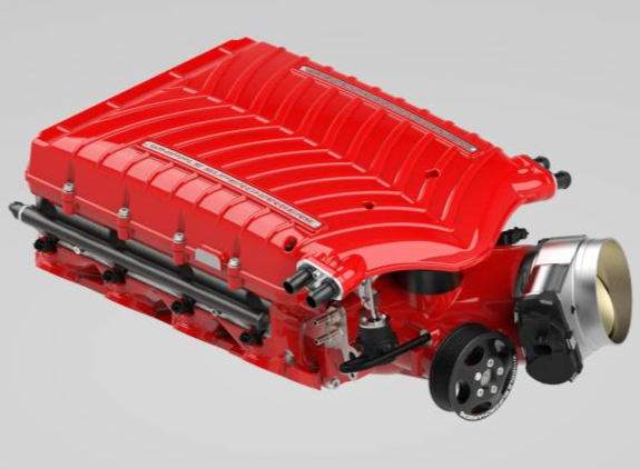
A supercharger made for various Chevrolet engines (Image courtesy of Whipple Superchargers)
Turbocharged Driving
Turbochargers are pressure-boosting systems more commonly seen in road and endurance racing. These systems increase inlet air or air mixture density by utilizing the energy from released exhaust gases. This works by using the exhaust gas to drive the turbine in the turbocharger which consequently drives the turbocharger’s compressor. This compressed air is then directed to the engine’s intake valve where it is mixed with the fuel spray. Opposite of superchargers, these systems are good at generating high-end power, which is beneficial for maintaining speeds through bends on a track or windy road and is why they are seen in cars such as the upcoming McLaren W1, the Chevrolet Corvette ZR1 and the upcoming ZR1X, and the Ferrari F80.
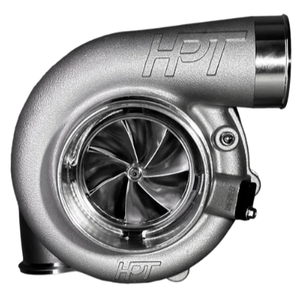
A turbocharger made to boost engine air compression (Image courtesy of HP Race Brands)
Regulating the Heart with the Mind
Despite advancements in manufacturing technology and engineering methods to minimize tolerances between parts and increase engine performance and longevity, modern day supercars and hypercars rely on computer-assisted technology to even further enhance their engine’s performance and reliability. These computers are used to regulate and optimize engine performance in a myriad of ways, including: fuel injection rate, variable valve timing/lift, engine coolant temperature, engine airflow, and the engine’s air/fuel mixture ratio. These computers are known as engine control units (ECUs) and regulate different engine functions through different types of controls.
Staying in the Loop
One way the ECU regulates the engine is through closed-loop control. This is a system which is used by the ECU to keep certain engine functions constant and to not allow them to fluctuate. Examples of this include the engine’s piston firing order, transmission shifts in automatic or dual-clutch transmissions, and the engine’s O_2 sensor readings.
Another way the ECU regulates the engine is through open-loop control. This is a system used by the ECU which helps monitor fluctuations in certain aspects of the ICE power plant. Items governed by open-loop control include fuel levels, oil levels, and temperature sensors throughout the engine.
ECUs can also use a combination of open-loop and closed-loop controls. This is more commonly seen when certain parameters of the ICE power plant fluctuate but are needed to remain constant and must be fixed by the engine’s software if the parameters are out of range. Items typically governed by this type of control system include fuel injection correction, variable-valve timing/lift, and turbo boost control.
A Cascading Effect
When certain engine tasks are too complex to be regulated by the loop controls as stated above, the ECU can employ what is known as a cascade control. This is used for tasks such as the engine’s air-fuel mixture or understanding the throttle position in relation to the engine’s current performance. Other tasks which carry the same level of complexity may also be regulated by the ECU’s cascade control systems.
Made to Handle Anything
Supercars and hypercars do not just stay in ideal conditions with low humidity and room temperature. Owners live in various climates, from humid tropical climates like Singapore, to dry and arid climates like Dubai, temperate and humid climates like Houston, Texas, or extremely cold environments like New York City and Chicago. No matter where the supercar and hypercar is bought and sold, it must be able to withstand these conditions, as does the car’s ECU. This is the reason why ECUs are meant to withstand environmental temperatures from -40° C to 125° C
Many of these supercars and hypercars will be driven in these environments, meaning that they will be subjected to the heat and fluids of the engine as well. They are typically designed to last 6,000 to 8,000 service hours and approximately 240,000 kilometers (km), or approximately 149,000 miles (mi). So, just like engine components are prone to wear, so are ECUs and they should be monitored regularly by trained and experienced personnel.
Adapting to the Terrain and Environment
As with most things in the modern age of artificial intelligence (AI), industry experts are testing to see if adaptive machine learning can be utilized to enhance the ECUs performance and output even more. An example of this is this study from the Society of Automotive Engineers where the goal is to use various programs to help the ECU determine the optimal regulating strategies to maximize engine performance. This can be beneficial not just for the ECU, but also for the longevity of the engine and the car itself.
An Electrified Force in Motion
In the world of supercars and hypercars, electric batteries and power plants are either working in tandem with internal combustion engines or are replacing internal combustion engines altogether. As mentioned in the introduction, examples of hypercars using this technology are the Ferrari F80 and the Rimac Nevera and Nevera R. Unfortunately for automotive purists who enjoy ICE power plants, electrification of cars isn’t going away anytime soon and is most likely here to stay.
A New Power Source
Similar to many hybrid vehicles which utilize batteries to maximize fuel efficiency, supercars and hypercars are utilizing lithium-based batteries to maximize performance. Once they’re on, they provide instant voltage to the car’s electric motor(s). It’s also important to note that lithium is the lightest of all metals, which is why lithium-based batteries are a top choice for manufacturers such as Ferrari. In terms of lithium-based batteries, the two most common types are Li-P and Li-I batteries.
A Stable Motoring Force
When the lithium-ion battery generates power in a supercar or hypercar, the power is transmitted to the electric motor. In the case of supercars and hypercars, the electric motor of choice is a permanent magnet (PM) brushless direct current (BLDC) drive motor. These motors work by using rare-earth magnets that spin at high rpms and generate large sums of power efficiently. PM BLDCs also achieve high efficiency since they do not need brushes in the motor that cause friction and, thus, lose energy. This technology is employed in cars such as the Ferrari Elettrica.
Energy at the Cellular Level
Using Positivity to Move Forward
Another type of source that can provide energy to electric motors are known as fuel cells. Fuel cells are structures that contain numerous cells. Each cell operates in a manner similar to a traditional car battery in that there is an anode electrode and cathode electrode. The positively charged ions move through the electrolyte in each cell from the anode electrode to the cathode electrode.
The difference in potential electrical energy between the higher potential electrical energy node (the anode) and the lower potential electrical energy node (the cathode) produces the fuel cell’s voltage (V). As the ions move across the electrolyte, an electrical current (I) is produced and travels from the anode to the cathode via a wire with a resistor (R) which helps regulate the flow of electrons. When you combine V with I, you get the following formula:
P = I * V
P: Power (Watts)
I: Current (Amperes)
V: Voltage (Volts)
Another way power from the fuel cell can be calculated is:
P = I^2 * R
P: Power (Watts)
I: Current (Amperes)
R: Resistance (Ohms)
and..
V = I * R
V: Voltage (Volts)
I: Current (Amperes)
R: Resistance (Ohms)
Since Ohm’s Law states that P = I * V and V = I * R, P = I * (I * R) which equals P = I * I * R, or P = I^2 * R.
In order for this process to work, fuel cells require a special type of liquid fuel that is different from petroleum-based gasoline or diesel. Fuels that power fuel cells include, but are not limited to:
-Methanol
-Molten Carbonate
-Phosphoric Acid
Needing to Breathe
The second component needed in fuel cells is oxygen or air from the environment. Along with electrical power the fuel cells also generate gas, which is released as exhaust from the cell.
Although this is a technology not widely used in supercars and hypercars as of this writing, it has potential benefits to extend driving range compared to lithium-based batteries and maximize the performance of the supercar’s or hypercar’s electric motor(s).

Figure 6: Diagram of a fuel cell to be used in a car
The Energy to Keep Going
Unfortunately, not all the energy generated from some power plants go directly to the driveshafts in supercars and hypercars but also to the various internal moving parts. The pistons, camshafts, crankshafts, and other moving parts inside the internal combustion engine all require energy to move. Engineers recognize this and do their best to keep ICE power trains as light and as well lubricated as possible to maximize energy efficiency and minimize energy losses. Furthermore, technology such as variable valve timing helps the engine use just the right amount of fuel to maximize energy efficiency, which also leads to greater fuel efficiency for the vehicle overall.
Engineers utilize the lightest materials possible in order to maximize fuel efficiency and reduce weight. The easier the internal combustion engine can move the car, the less fuel the engine requires to operate effectively. This is also why so many auto manufacturers focus on power to weight ratios: the higher the number, the more power is used for driving.
The topic of energy efficiency in general is why technologies such as lithium-based batteries and fuel cells have gained more attention over the past few years. These systems produce instant power and are very efficient in using their energy. Many believe that utilizing these methods will increase vehicle energy efficiency and decrease energy consumption and waste.
The Cost of It All
The Upfront Costs
As one can imagine, ICE power plants in supercars and hypercars aren't cheap. They’re made from the finest materials to push the bounds of what is possible in high-performance vehicles. They also are meticulously designed and built to withstand the most extreme temperatures and forces. When accounting for the materials and specialized labor needed to design and build these engines, the costs for these powerplants can easily be tens if not hundreds of thousands of dollars. These costs ultimately reflect the balance between innovation, durability, and affordability — a trade-off every automaker must navigate.
As with all machines, parts and components do wear over time. This is a result of fatigue failure, which is when a machine is used so often that either certain sections of a component that experiences high stresses over long periods of time begins to crack, or due to the fact that crankshafts, camshafts, and bearings wear out from making so many revolutions over a long period of time. However, engineers do their best to minimize wear and tear. Many use finite element analysis (FEA) for parts that experience great amounts of stresses and forces to prevent the component from tearing. Engineers also determine how long rotating parts will last by conducting a series of tests to see how many revolutions the parts can withstand and create a lifetime estimate for those parts based on internal testing.
Since electric motors, electric batteries and fuel cells still seem to be a relatively new technology, time will tell how long these batteries and fuel cells will last. They do seem to carry a cost advantage when it comes to utilizing energy. However, as witnessed in the Rimac Nevera, electric powertrains can also be costly and is a major reason why the car commanded a $2.2 million price tag.
Paying for the Upkeep
All machines begin with the need to buy something because it’s either needed or wanted. It serves its intended purpose for a certain period of time until the machine begins to start breaking down. Once the costs become too much, most believe it is time to get rid of the car. This is what’s known as the life-cycle costs. It’s no different for supercars and hypercars and is something all owners have to face when the time comes.
Along with life-cycle costs are costs known as variable costs. As the name suggests, these costs fluctuate as time passes. These costs include the maintenance needed to keep the car running as well as any repairs as a result of the wear and tear on the supercar or hypercar. While not a topic that’s enjoyable to discuss and talk about when it concerns an iconic supercar or hypercar, these vehicles are still machines and will eventually cost significant sums of money to maintain.
Fastening Everything Together
From the Benz Patent Motor Car, model no. 1 to the Rimac Nevera R and the Ferrari F80, automobiles relied on powertrains to get people from Point A to Point B. As the world’s population still continues to grow and parts of the world experience higher standards of living, more resources will be required to meet these demands. However, the demand for cars has never been higher, and automotive enthusiasts demand internal combustion engines to remain in the auto industry.
Nevertheless, engineers must create powertrains which best utilize available resources and must also be cost effective. Future powertrains must continue to be innovated to place less strain on energy resources and create fewer emissions. Looking into methods which reuse or recycle defunct engines could potentially preserve or reduce the need to mine for more resources.
How would you improve existing or even proposed powertrains? How should we handle ICE powertrains in the future? What other powertrain types should OEMs use in their supercars and hypercars? Let us know what you think in the comments below!
Additional References:
Ali, Salah H.R. Automotive Engine Metrology. Pan Stanford Publishing Pte. Ltd, 2017
Ehsani, Mehrdad et. al. Modern Electric, Hybrid Electric, and Fuel Cell Vehicles. CRC Press. Taylor & Francis Group, 2018
Heywood, John B. Internal Combustion Engine Fundamentals. McGraw-Hill Education, 2018
Reif, Konrad et. al. Automotive Handbook, 11th Edition. © Robert Bosch GmbH., 2022
Get a quick dose of inspiration from Unifunful Today here
See our thought-provoking articles from Everyday Engineering here and investigate the engineering behind everyday items and places
See more articles from Engineering in Motion here to see how engineering moves us around the world
Missed last week? No worries, we got you! See what we covered last week and more in our weekly status reports here
Discover the vision and values guiding the Unifunful mission here
First time visiting Unifunful? Become familiar with the history and foundation Unifunful was built on here
Meet the contributors who make Unifunful possible here